1. Membrane stress — PD/2t
Pressure inside a thin cylinder is carried by tension in the wall, spread evenly through the thickness — membrane stress. Cutting the shell in half and balancing the pressure force against the wall force gives the hoop stress; doing the same across the shell gives the longitudinal stress, which is half:
The hoop stress governs, so it sets the shell thickness. ASME Section VIII Division 1, UG-27 uses the same balance on the inside radius R, with a small correction for the wall thickness:
Try it
These relations assume a uniform wall loaded only by pressure. They say nothing about a force or moment applied at one spot — a nozzle, a clip or a support.
2. Local stress at an attachment
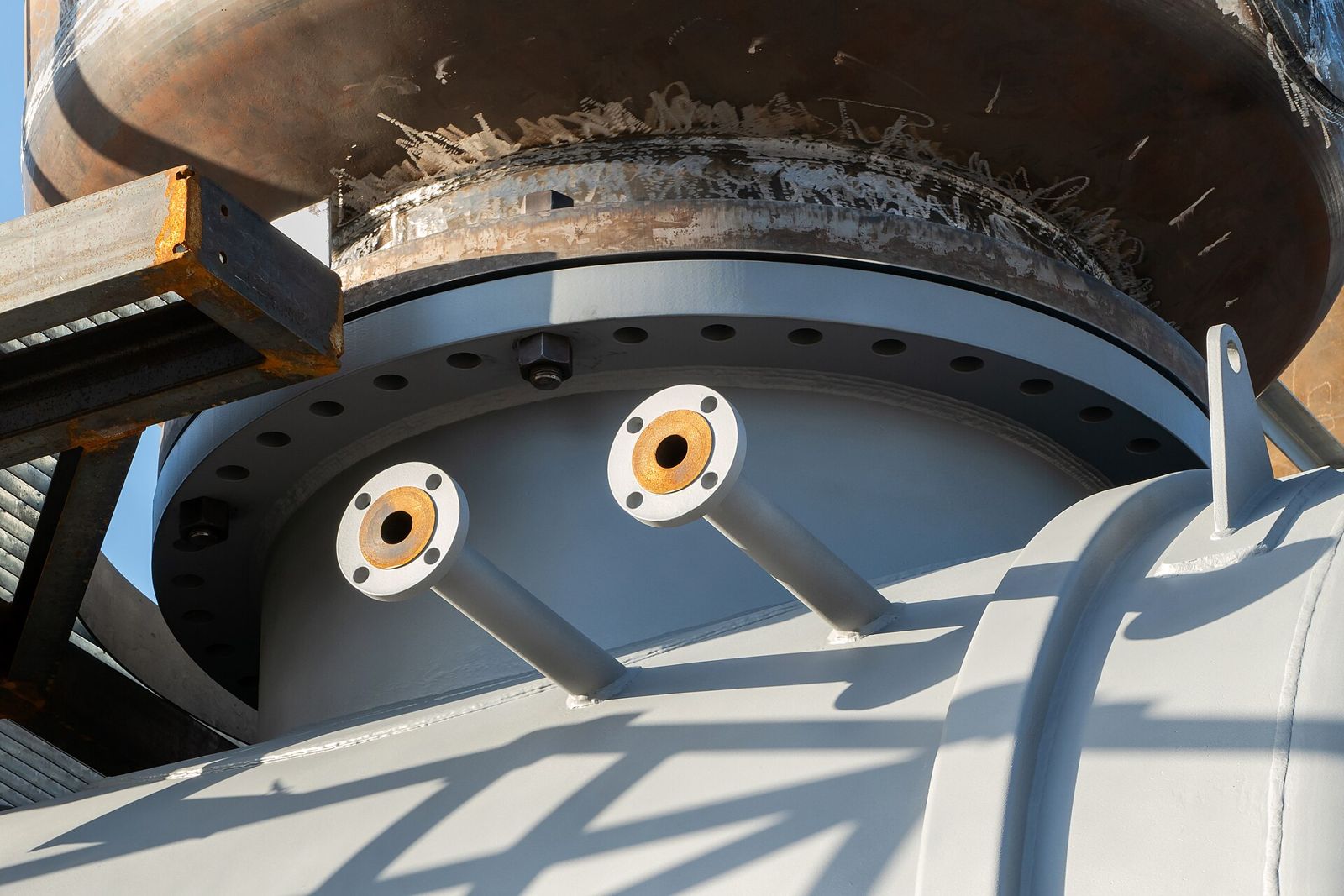
Piping, platforms and supports push, pull and bend the shell through the parts welded to it. The load enters the wall over the small area of the attachment, so the shell bends locally as well as stretching. Bijlaard solved this for a rigid attachment on a cylinder and on a sphere; the Welding Research Council published the results as charts in WRC 107 and later as equations in WRC 537.
Six load components act at the attachment: the radial load P, two moments MC and ML, two shears VC and VL, and torsion MT. The radial load and moments give a membrane force N and a bending moment M per unit length in the shell wall, and the stress at a surface is
The ± is the bending: it adds on one surface and subtracts on the other, which is why every point is checked on the outer and the inner surface. The shears and torsion add shear stress. Both methods in this tool answer the same question — this stress, at this attachment — and differ only in how they get there.
Pick a load to see which points it stresses
ML — longitudinal moment
Rocks the attachment along the vessel; one of A, B goes into tension, the other into compression.
Red and blue mark the pair that goes into tension and compression; which is which depends on the direction of the moment. Each point is checked on the outer (u) and inner (l) surface.
3. Decay length
Local bending in a shell does not spread far. Moving away from the load it oscillates and dies out exponentially, with the length scale λ = √(Rm·T):
Distance x is measured from the edge of the attachment. At x = 2.5λ the envelope is down to about 4 % of its value there, so the local effect is essentially gone. This one number governs both halves of the tool: it is why the bulletin assumes each attachment stands alone, and it is the distance the finite element mesh is refined across.
Change the radius and thickness
A thin, small-radius shell has a short zone; a thick, large one a long zone.
LA · Local analysis
The bulletin method — WRC 537
Closed-form shell theory, curve-fitted and published as equations. Seconds to run, every coefficient traceable to a figure in the bulletin, and bounded by the range those figures were drawn over.
4. The bulletin method
The bulletin reduces Bijlaard's solution to dimensionless coefficients read against two parameters: the shell parameter γ = Rm/T and the attachment parameter β — for a round attachment β = 0.875 ro/Rm, and for a rectangular one a pair of ratios formed from the two side lengths. Each load component has its own coefficients for membrane and for bending, in the circumferential and the longitudinal direction.
Stresses are evaluated at four points round the attachment edge — A and B on the longitudinal axis, C and D across it — on the outer and the inner surface, giving eight values. At each point the contributions of every load are summed with their signs, then combined into a stress intensity. Nothing between those points is computed: the method assumes the governing stress is at the attachment edge, which is where the shell theory puts it.
Coefficients are interpolated from the published curves. Every interpolation this tool performs is shown in the report, with the figure or table it came from and the values either side, so the number can be checked by hand.
5. Reinforcing pads
A pad thickens the wall under and around the attachment, lowering the stress at the attachment edge but creating a second edge — the pad edge — where the shell is back to its own thickness. Both are checked:
- At the attachment edge, with the shell and pad thickness together.
- At the pad edge, with the shell thickness alone and the pad as the attachment.
Either can govern.
6. Acceptance limits
Stresses are sorted by what they can do. Membrane stress from the attachment loads could, if too high, let the shell yield through — it is local primary stress. Bending at the attachment is self-limiting — it relaxes once the material yields locally — and is treated as secondary. The limits are multiples of the allowable stress S at the design temperature:
Move the stresses against the limits
The 3S limit is the one this tool applies. ASME VIII Division 2 (5.5.6) allows the larger of 3S and 2Sy in some cases; that is not used here. S is entered by the user and is not checked against code tables.

7. Limits of the bulletin method
- The coefficients come from charts of γ = Rm/T and the attachment size β. For a cylinder the charts run from γ = 5 to 300 and up to β = 0.5, with a rectangular attachment's sides no more than 4 : 1. Outside that range this tool holds the value at the chart edge and warns — the result is then an extrapolation.
- The attachment is taken as rigid and on its own — away from heads, cone junctions and other nozzles (see the decay length).
- Stresses come out at the attachment edge only, not as a full stress field.
- Only the shell is checked. The nozzle neck, the weld and the attachment itself need their own checks.
- A nozzle on a cone is treated as a cylinder at the local cone radius, and is flagged as approximate.
- Loads are external loads; internal pressure is added separately.

Cases outside these limits need a model of the actual geometry — the second half of the tool.
FE · Finite element
The shell model
A numerical model of the geometry as drawn, meshed from the same inputs. Geometry, meshing, the mesh-quality check and the solver are built and in early access; section 13 says exactly where that stands.
8. Shell idealisation
The vessel is represented by its mid-surface and meshed with four-node quadrilateral shell elements. Thickness is a property of the element rather than something the geometry has to resolve, so a single layer of elements carries membrane force and bending moment together.
Shell elements are the right choice here and not a compromise. The shells this tool covers run from γ = Rm/T of about 5 upward — thin enough for shell theory to hold — and the quantity being checked is exactly what a shell element reports. Solid elements would need several layers through the thickness to recover the same bending, at many times the element count, and would then have to be linearized back to membrane and bending to be compared with the code limits.
- Parts that meet share nodes. The nozzle barrel, the pad and the shell are welded at the intersection curve, so load crosses the junction through the mesh itself — no constraint equations, no contact pairs, nothing to tune.
- A reinforcing pad is modelled as integral with the shell: the section under the pad carries the shell thickness plus the pad thickness. The pad edge therefore appears as a step in section, which is where its own stress concentration comes from.
- Corrosion allowance is taken off each component before its mid-surface and section are formed.
- A nozzle can penetrate the shell or sit on it unpierced, as a trunnion or pipe support does.
9. The structured mesh
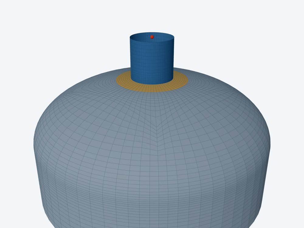
The mesh is structured and all quadrilateral — no triangles, no automatic tetrahedral fill, and no decisions left to the user beyond an overall size factor and a growth ratio. Each surface is meshed as a chart:
- Plate — a flat plate: one rectangular grid.
- Band — a cylinder or cone: a meridian-by-circumference grid, closed around the circumference.
- Cap — a head or circular plate with the attachment near the pole: a planform square grid holding the attachment, a ring out to a circle, then rows down to the shell end.
- Cap and band — a head with the attachment away from the pole: a plain cap, then a band holding the attachment whose columns blend from the cap's spacing to the attachment's.
An opening is cut with an O-grid. A rectangle of the surrounding grid is replaced by rings running in to the exact barrel-to-shell intersection curve — and to the pad edge when a pad is fitted — and the barrel is then built upward from those same intersection nodes. The junction is one continuous mesh, graded into the opening rather than stitched across it. A structural clip is extruded plate by plate from grid lines on the shell surface.
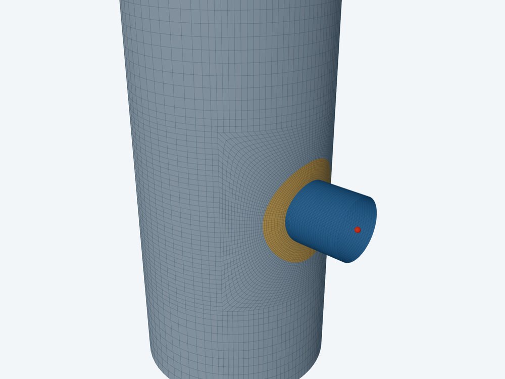
Element size follows the decay length λ = √(R·T) rather than a fixed count:
Away from the junction the spacing grows geometrically and is capped, so the refined band is dense where the gradient is and the far field is not wasted. The first element being smaller than √(R·T) at a discontinuity is the same rule the established nozzle-FEA tools apply.
10. Mesh quality checks
A mesh that looks right can still be unusable, so every model is checked before it is offered, element by element, at warning levels of the kind NASTRAN's GEOMCHECK uses:
| Metric | Warn | Fail |
|---|---|---|
| Aspect ratio | > 5 | > 10 |
| Skew | > 45° | > 60° |
| Warpage | > 5 | > 10 |
| Scaled Jacobian | < 0.7 | < 0.5 |
| Size jump to neighbour | > 1.5 | > 2 |
Three further checks are about the model rather than the element shape:
- Free edges. An edge used by only one element, and not on a boundary the model is meant to have — a shell end, a plate edge, a nozzle end, a clip top — is a gap between parts. Any found are drawn in the 3D view so they can be seen, not just counted.
- Orientation. Neighbouring elements must walk their shared edge the same way, so element normals are consistent across each part and pressure acts on one face.
- Refinement. The number of element rows crossing 2.5λ and the first element size at the junction, on the shell and on the nozzle — the check that the mesh is fine enough where the answer comes from.
A mesh with folded or collapsed elements — worst scaled Jacobian at or below 0.05 — is rejected outright rather than passed on, with the reason and what to change.
11. Linearization and categories
ASME VIII Division 2, Part 5 asks for stresses split through the thickness into a membrane part, a bending part and a peak, then sorted into categories with their own limits. With solid elements that split takes an explicit linearization along a stress classification line. With shell elements it comes out directly: the element already reports the membrane force N and the bending moment M per unit length, so
The categories and their limits are the same ones the bulletin half is checked against:
- Pm — general primary membrane, remote from the attachment. Limit S; this is the pressure design of the shell.
- PL — local primary membrane at the attachment. Limit 1.5S.
- Pb — primary bending. Q — secondary, self-limiting. Together, limit 3S.
- F — peak, at the weld toe notch. Fatigue only, and a shell model does not resolve it; it needs a solid submodel or a fatigue method of its own.
What the field buys you over the bulletin is that the governing point is found rather than assumed. The bulletin reports four points because shell theory says that is where the peak is for an isolated attachment; once the attachment is near a seam, a cone junction or its neighbour, that is no longer reliable. A model also reports the nozzle and the pad, not just the shell.
12. The handover point
The two halves are not alternatives to pick between on taste. The bulletin method is the right answer whenever it applies, because it is quicker, reproducible and checkable by hand. The model is for the cases where it does not. The calculator says which it is: when a case falls outside the bulletin, the results screen says so and offers to carry the same inputs across.
- γ or β outside the charted range, where the bulletin value has had to be held at the chart edge.
- An attachment within 2.5λ of a head, a cone junction, a seam or another attachment.
- Large d/D, where the opening is no longer small compared with the shell.
- Geometry the bulletin never charted — obround openings, structural sections, tilted and tangential nozzles.
- A nozzle on a cone, where the bulletin answer rests on an equivalent-cylinder approximation.
- Stresses wanted in the nozzle or the pad, not only in the shell.
- A code route that calls for design by analysis rather than design by rule.
13. Status of the FE half
Stated plainly, because a method note that overstates what is built is worth nothing:
- Built and in the product. The geometry kernel, the structured mesher, the mesh-quality check and the 3D view — everything described in sections 8 to 10.
- Built, in early access. The shell-element solver and its ASME VIII-2 Part 5 elastic checks: primary and primary-plus-secondary stress, fatigue, linear buckling, ratcheting by the Bree diagram, and thermal load cases; and the limit-load analysis of 5.2.3 (elastic-perfectly plastic, small displacement), on the VIII-2 route only. Early access is by invitation.
- Under verification. Each of those results is being checked against reference solutions and an independent solver. Until that is finished, FE results are not a source of design values.
- Not attempted. Elastic-plastic analysis with large displacement (5.2.4), the elastic-plastic local strain and ratcheting checks, contact, and dynamic loads.
The WRC 537 half is complete and is what the calculator returns results from today. Section 7 is the honest limit of that answer, and section 12 is what a case does when it falls past it.
References
- WRC Bulletin 107 — Local Stresses in Spherical and Cylindrical Shells due to External Loadings.
- WRC Bulletin 537 — Precision Equations and Enhanced Diagrams for Local Stresses in Spherical and Cylindrical Shells due to External Loadings.
- ASME BPVC Section VIII, Division 1 — UG-27, UG-22 and U-2(g).
- ASME BPVC Section VIII, Division 2 — Part 5, Design by Analysis; 5.2 stress categories; 5.5.6 limits.
- Bijlaard, F. P. — Stresses from local loadings in cylindrical pressure vessels, Trans. ASME, 1955.