PD/2TCalculators
menu
FEXLAFinite Element × Local Analysis

The attachment checks your vessel program leaves out

Local stress analysis for pressure vessel nozzles, lugs and supports. FEXLA is a set of tools for pressure vessel engineers: each one checks one kind of job, shows its working, and gives you a report you can file.

Under FEXLA

  • Nozzles and clipsLocal stress where an attachment is welded to a shell, by the standard bulletin method and by a finite-element model.
  • Lifting and tailing lugsThe lift worked step by step, the lug plate checked, then the lug on the shell.
  • Air-cooler headersPlug headers and welded boxes: ligaments, stays, end plates and the pressure rating.
  • Agitators, skirts and bucklingThe special cases that have no simple formula.
  • Pipe AtlasPipe, flange, fitting and gasket tables. Free, no sign-in.

Free during early accessComplex tools, by invitation

What you can use today

Three free tools, and the finite-element tools

  • Free, no sign-in

    Pipe Atlas

    Pipe, flange, fitting and gasket dimensions from the standard tables, with pressure ratings. Open it and look things up.

    Open Pipe Atlas
  • Free during early access

    WRC 537 calculator

    Local stress where a nozzle or clip is welded to a shell. Every coefficient is shown, so a reviewer can follow the number.

    Open the calculator
  • Free during early access

    Lifting and tailing lugs

    Check a lifting lug, a trunnion or a tailing lug for a vertical or a horizontal vessel: the lug, its weld, the shackle, the shell under it, and a report with a checklist.

    Open the lug calculator
  • Not free, by invitation

    The finite-element tools

    Where the standard method stops, the same case opens as a model of the shell. Priced separately, and open to invited engineers while we verify the results.

    Ask about access

Try it

Check a nozzle here, no sign-in

This runs the same WRC 537 calculation as the calculator, in your browser. Change a number and the checks move.

Nozzle with a 420 × 16 mm pad on a cylinder

Result

PASS

Nozzle edge, Pl against 1.5S92.9 / 207 MPa
Nozzle edge, Pl + Pb + Q against 3S96.0 / 414 MPa
Pad edge, Pl against 1.5S59.5 / 207 MPa
Pad edge, Pl + Pb + Q against 3S67.7 / 414 MPa
Nozzle neck, longitudinal Pm12.5 / 138 MPa

WRC 537 local stress at the nozzle and pad edges, against the ASME VIII-2 limits. 2 engine notes are in the full report. A quick check, not a design record.

The report

A calculation report you can file

Every check ends in a report that shows its working, so the next engineer can check it without asking you. Slide through a sample.

Sample report, page 1 of 6. Invented data, to show the layout of a report. Not a real vessel.

  • Nozzle local stress, WRC 537Page 1 of 6

    Summary

    Nozzle N3 on shell V-101

    Local stress at a round nozzle with a reinforcing pad, by WRC 537.

    Result

    PASS

    All checks are within their limits. The highest ratio is 0.45, local primary membrane stress at the nozzle edge.

    MethodWRC Bulletin 537
    AcceptanceASME VIII-2 Part 5 limits
    UnitsSI (mm, MPa, N)
    Material, shell and padSA-516 Gr 70
    FEXLA · Sample projectSample, invented data
  • Nozzle local stress, WRC 537Page 2 of 6

    Input data

    Shell inside diameter1800 mm
    Shell thickness22 mm
    Corrosion allowance3 mm
    Allowable stress, S138 MPa
    Design pressure1.2 MPa
    Design temperature150 °C
    Nozzle outside diameter273.1 mm
    Nozzle wall thickness12.7 mm
    Pad outside diameter420 mm
    Pad thickness16 mm

    External loads at the junction

    Radial load, P2000 N
    Shear, VL and VC1500 N, 1500 N
    Moments, ML, MC, MT2, 1.5, 1 kN·m
    FEXLA · Sample projectSample, invented data
  • Nozzle local stress, WRC 537Page 3 of 6

    Geometry parameters

    The bulletin works from the shell mean radius, the thickness at the nozzle edge and the size of the attachment.

    Mean radius912.5 mm
    Rm = (ID + T) / 2
    Thickness at the nozzle edge35 mm
    T = shell + pad − corrosion
    Shell slenderness26.07
    γ = Rm / T
    Corroded nozzle radius133.55 mm
    r0 = OD/2 − CA
    Attachment ratio0.128
    β = r0 / Rm

    Pressure stress in the shell: hoop 57.03 MPa, longitudinal 28.52 MPa.

    FEXLA · Sample projectSample, invented data
  • Nozzle local stress, WRC 537Page 4 of 6

    Stresses at the nozzle edge

    MPa. A to D are the four points round the nozzle; u is the outer surface, L the inner.

    PointσφσxτCombined
    A outer85.320.60.3685.3
    A inner94.735.00.3694.7
    B outer95.933.60.1596.0
    B inner89.924.10.1589.9
    C outer49.340.90.1549.3
    C inner63.649.20.1563.6
    D outer62.048.60.3662.0
    D inner52.443.60.3652.5

    Highest combined stress 95.95 MPa at point B, outer surface. The pad edge is lower, at 67.7 MPa.

    FEXLA · Sample projectSample, invented data
  • Nozzle local stress, WRC 537Page 5 of 6

    Acceptance

    Nozzle edge, Pl against 1.5S92.93 / 207 MPa
    ratio 0.45PASS
    Nozzle edge, Pl + Pb + Q against 3S95.95 / 414 MPa
    ratio 0.23PASS
    Pad edge, Pl against 1.5S59.46 / 207 MPa
    ratio 0.29PASS
    Pad edge, Pl + Pb + Q against 3S67.7 / 414 MPa
    ratio 0.16PASS
    Nozzle neck, longitudinal Pm12.49 / 138 MPa
    ratio 0.09PASS
    Nozzle neck, shear1.57 / 96.6 MPa
    ratio 0.02PASS
    FEXLA · Sample projectSample, invented data
  • Nozzle local stress, WRC 537Page 6 of 6

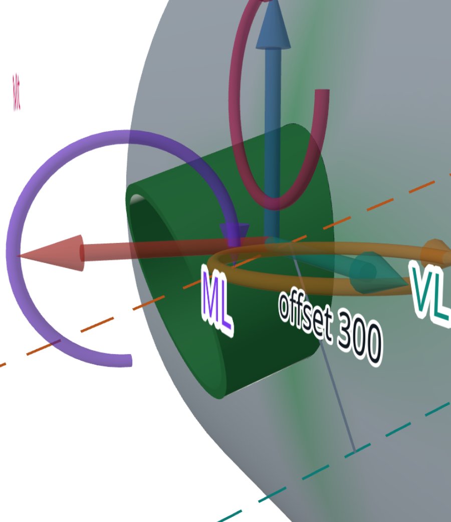
    Model figure

    Model of a nozzle on a cylindrical shell from the WRC 537 calculator, the nozzle in green with the load axes

    After Run Analysis the calculator draws the case to scale: the shell, the nozzle in green and the loads where they act. The same figure is placed in the report. This one is an example from the calculator, not this sample case.

    FEXLA · Sample projectSample, invented data

Where it applies

Local stress and attachments on pressure equipment

Wherever something is welded to a shell and its load has to go into the wall.

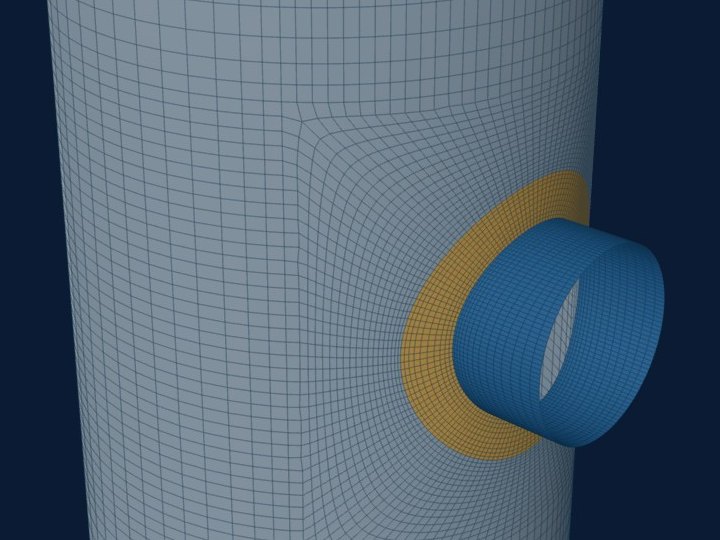
  • Model of a large-diameter pad-reinforced nozzle on a cylindrical vesselFEXLA model
    Large-diameter nozzleA pad-reinforced nozzle close to the size of the shell, where the closed-form charts run out and the shell model takes over.Attachment analysis
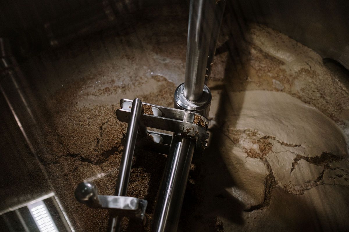
  • Mixer shaft and impeller turning inside a stainless steel vessel
    Agitator nozzle on a top headWeight, thrust, torque and rotating bending on a nozzle in a head, with the fatigue cycles that come from running hours.Agitator notes
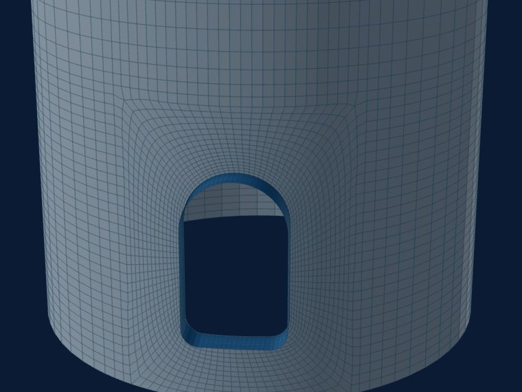
  • Model of a skirt with a tombstone access openingFEXLA model
    Tombstone opening in a skirtAn access opening in a support skirt under weight and wind or seismic moment, with its sleeve and the buckling check.Skirt opening notes
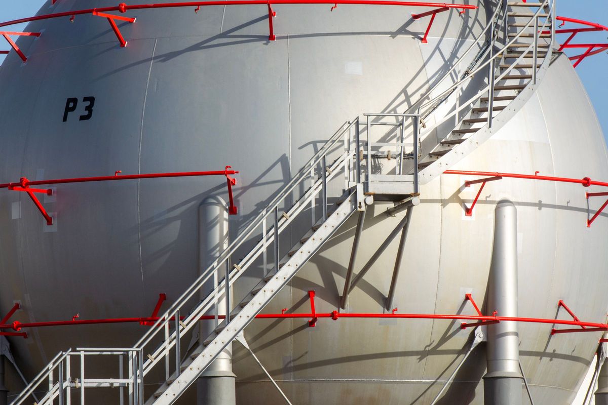
  • Spherical pressure vessel with a stair, platform and handrail brackets welded to the shell
    Platform and stair clipsBrackets, platform clips and handrail supports welded to a vessel shell, each passing its load into the wall.Local stress notes
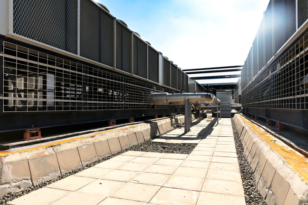
  • Rows of industrial air-cooled fan units along a walkway
    Air coolersAPI 661 plug headers and welded boxes: ligaments, stays, end plates and the pressure rating.Header analysis
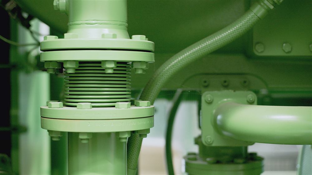
  • Flanged pipe connection with expansion joint
    Pipe AtlasPiping loads at a nozzle, and the pipe, flange and gasket tables to size the connection.Pipe Atlas

Learn

Notes on how each check works

Written from what the programs actually compute, with the equations and a worked number.

All method notes

Questions

Questions engineers ask

About FEXLA

What is FEXLA used for?

Checking the local stress where something is welded to a pressure vessel: nozzles and clips by WRC 537 and by a finite-element shell model, lifting and tailing lugs, agitator nozzles, skirt openings and API 661 air-cooler headers to ASME VIII-1 Appendix 13.

Is it suitable for pressure equipment design work?

The WRC 537 calculator is complete and shows every coefficient and code paragraph. The finite-element modules are in early access for invited engineers and are under independent verification; until that is finished their results are not a source of design values.

Which codes and standards does it follow?

WRC Bulletin 537, ASME VIII-1 (UG-27 and Appendix 13), ASME VIII-2 Part 5 (stress categories, 5.2.3 limit-load, 5.4.2 buckling, 4.5.17.3), Moss procedures 10-3 to 10-8, and ASME BTH-1 and B30.26 for lifting lugs.

Does it replace my vessel design program?

No. Shell thickness and opening reinforcement for pressure are sized in your vessel program. FEXLA checks what is attached to the shell and the loads it brings.

Where it applies

Which nozzles and shells does the WRC 537 calculator cover?

On a cylinder: a round nozzle, radial or hillside, or a rectangular clip. On a cone: a round nozzle. On a formed head: a round nozzle in the spherical region. A reinforcing pad is optional on each.

Can it check platform clips, pipe supports and ladder brackets?

Yes. Rectangular clips and the brackets that carry platforms, pipe supports and ladders are checked with the clip calculator, by WRC 537. Structural sections and clips close to a seam or another attachment go to the finite-element shell model.

Can it check lifting lugs and tailing lugs?

Yes. It steps the lift through its angles, finds the load at each lug, checks the plate to Moss and AISC and to BTH-1, checks the shackle fit, and then builds a shell model of the governing lug. Trunnions, a tail beam and two offset lugs are covered; a base ring is checked by hand.

Can it check an agitator nozzle?

Yes. A nozzle on a top head carrying an agitator, under its weight, thrust, torque and rotating bending moment, with the fatigue cycles worked out from speed, running hours and the number of starts.

Can it check API 661 air-cooler headers?

Yes, plug headers and welded rectangular boxes to ASME VIII-1 Appendix 13: the stress at each location, the tube-hole ligaments, end plates and stays, the required thickness, the MAWP and the test condition. Nozzle and support loads on the header are not covered; check a header nozzle as an attachment.

Can it check an opening in a skirt?

Yes. A tombstone, obround or round access opening in a support skirt, with its sleeve and an optional pad, under weight and wind or seismic moment, with the ASME VIII-2 4.5.17.3 hand checks beside the shell model. The base ring, gussets and anchor chairs are not modelled.

What it can do

Which loads can I apply at a nozzle?

All six components of the bulletin: a radial load, two shear forces, two bending moments and a torsional moment. You can give them at the shell junction or at the end of the nozzle, and the calculator carries them to the junction. Pressure is added to the local stresses.

When do I need the finite-element model instead of WRC 537?

When the bulletin stops: a case outside its charted range, an attachment close to a head, a cone junction, a seam or another attachment, a large opening for the shell, a tilted or tangential nozzle, an obround opening, or stresses wanted in the nozzle or the pad. The calculator tells you when a case falls outside the bulletin and offers to carry it across.

What else can the finite-element tools check?

Eigenvalue buckling to VIII-2 5.4.2 and an elastic-perfectly plastic limit-load check to 5.2.3. Large-displacement analysis, local strain limits and elastic-plastic ratcheting are not done yet.

Which materials and units does it use?

A list of common ASME II-D materials with the allowable stress taken at your design temperature, or your own material and allowable stress. Metric and U.S. units both work, and you can switch between them.

What does a nozzle check return?

The stresses at every evaluation point, the pass or fail against 1.5S and 3S, a 3D model of the case and a calculation report. You can save the case to your history and download the report as a PDF.

Is Pipe Atlas free?

Yes. Pipe Atlas, with ASME B36.10M and B36.19M pipe, B16.5 and B16.47 flanges, B16.9 fittings, ratings and gaskets, needs no sign-in.

What does it cost?

Pipe Atlas is free and needs no sign-in. The WRC 537 calculator and the lifting and tailing lug calculator are free during early access, and every new account is reviewed before it is opened. The finite-element tools are not free: they are priced separately and open to invited engineers, so ask us about access.

Pricing

The WRC 537 calculator, the lifting and tailing lug calculator and Pipe Atlas are free during early access. The finite-element tools are not free.

Individual

WRC 537 calculator, lifting and tailing lug calculator, Pipe Atlas and your own history. Every new account is reviewed before it is opened.

Free during early access

Request access

Finite-element tools

Lugs, headers, agitators, skirts, buckling and limit-load. Early access, for invited engineers.

Priced separately

Ask about access

Team

Shared calculations, materials library, reviewer sign-off.

Not yet available

Contact

Run the check. File the report.

Local stress at nozzles and clips, lifting and tailing lugs, skirt openings, air-cooler headers. Enter the vessel and the loads; the stresses, the pass or fail and a report ready for the file come back together.