A shell carries load in two ways: by membrane action, a stress that is even through the wall and stretches the mid-surface, and by bending, a stress that changes through the wall from tension on one face to compression on the other. Curved shells carry pressure mostly by membrane action, which is why they can be thin. Bending appears where the shape or the load forces the wall to change its curvature, such as at joints, flat parts and attachments.
This article shows why curvature favours stretching, where a shell has no choice but to bend, and how a computed stress is split into its membrane and bending parts before it is checked.
Stretching and bending
Cut a strip of wall one unit wide. Whatever loads it carries can be summed into a force along the mid-surface, N per unit length, and a moment, M per unit length. The force spreads evenly over the thickness; the moment needs a stress that changes sign through it. For a wall of thickness t:
Membrane action uses all of the metal at the same stress. Bending uses the faces fully and the middle hardly at all, so for the same peak stress a wall carries far less by bending than by stretching. A thin wall is good at one and poor at the other: N grows with t, but the moment it can take grows with t².
Why curvature favours stretching
Put pressure on a curved wall and the pressure can be balanced by tension along the curve. Each small piece of a cylinder is pulled outward by p and held by the hoop tension at its two edges, which meet at a slight angle. Nothing needs to bend. The classic result is the hoop membrane force and stress:
A flat plate has no curve for tension to work along. Pressure on it can only be carried by shear and bending, with the plate sagging between its supports. The difference is large, as the numbers below show.
Where a shell has to bend
A curved shell carries pressure by stretching only where nothing disturbs it. Bending appears wherever the shell is forced to change its curvature:
- Joints between different shapes, such as a cylinder and a head or a cylinder and a cone, where the two parts would grow apart if they were free.
- Flat parts: flat heads, flat cover plates and the flat sides of a box, which have no curvature to work with.
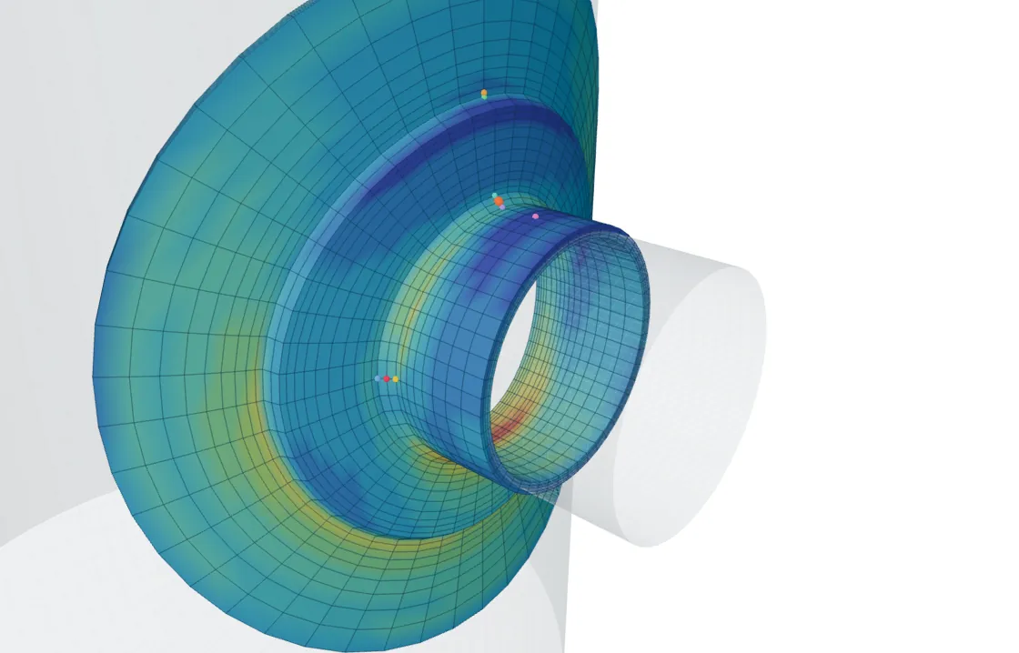
- Attachments: a load at a nozzle or clip bends the wall round the patch it acts on.
- Thickness changes, out-of-roundness and peaking at weld seams, where the mid-surface is not where an ideal shell would put it.
In each case the bending is local. It fades within a few times √(R·t) of the cause, and beyond that the wall goes back to membrane action.
Splitting a computed stress into the two
A model of a shell made of shell elements reports membrane and bending directly, because those elements are built from N and M. A solid model gives the full stress at every point through the wall instead, and that distribution is rarely a straight line. To check it, the stress is taken along a line through the wall and split into three parts. With x measured from one face:
This is called linearisation. The membrane and bending parts carry the whole force and moment on the section; the peak is a self-balancing remainder, usually a sharp rise near one face at a notch or weld toe.
Why the split matters
Membrane and bending get different limits because they fail differently. A wall that yields in membrane is yielded right through, and further load simply stretches it. A wall that yields in bending yields first at the faces only. The middle is still elastic, and the section can carry about half as much moment again before it is yielded through.
That reserve is why design-by-analysis rules typically allow primary membrane plus bending to reach about 1.5 times the allowable stress used for general membrane. Local membrane stress, which is confined to a small region, gets a similar typical increase. The values are code-specific, so check your governing code.
Key points
- Membrane stress is even through the wall; bending stress changes sign from face to face.
- Curved shells carry pressure mainly by stretching, which is why they can be thin.
- Flat parts, joints, attachments and thickness changes force the wall to bend locally.
- Linearisation splits a through-wall stress into membrane, bending and a self-balancing peak.
- Bending gets a higher typical limit than membrane because a bent section has a plastic reserve.
Where this matters in practice
- Shell-to-head and cone junctions, where bending adds to the membrane stress close to the joint.
- Flat heads, cover plates and box headers, which carry pressure mainly by bending.
- The shell round a nozzle or clip, where the local load produces both membrane and bending stress.
- Reading results from a solid model, where each check needs the stress linearised through the wall.
FEXLA reports the local stress at a nozzle or clip as membrane and membrane-plus-bending values and compares each with its limit.
See the nozzle checkRelated principles
- Stress categories and their limitsHow the stress categories combine into checks, and why each check has its own limit.6 min read
- Local loads on pressure vessel shellsHow a shell carries a push and a bend at a nozzle, how far the stress reaches, and how it splits through the wall.7 min read
- Stress concentration and the weld toeHow a hole, a notch or a weld toe lifts the stress over a small zone, and why that zone matters for fatigue.6 min read
Next principle: Stress concentration and the weld toe
Educational article. It explains principles and is not design guidance; follow your governing code and edition.