A structure collapses when yielding has spread so far that it can keep deforming with no increase in load, which is usually well after the first point yields. The load at which that happens is the limit load: a beam reaches it when enough plastic hinges form to turn it into a mechanism, and a pressurised shell when yield has spread through the wall over a large enough zone.
This article follows yielding from the first fibre to a full mechanism in a simple beam, then shows how the same idea applies to shells and how a collapse load is read from a load-deflection curve.
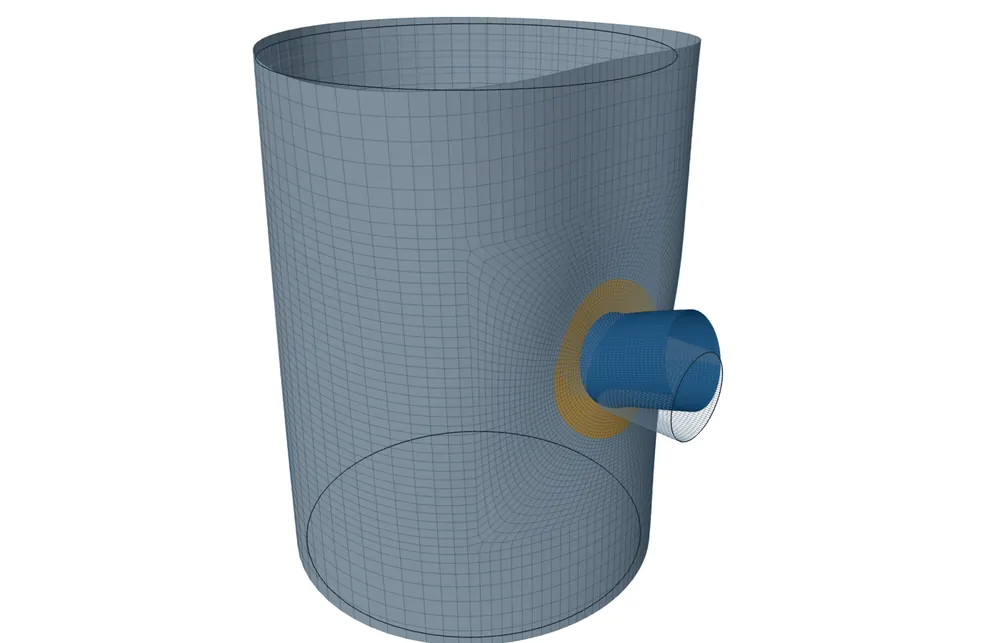
First yield is not collapse
Take a ductile steel idealised as elastic-perfectly plastic. When a beam is bent, the outer fibres reach yield first. At that load the section is far from used up: the metal nearer the middle is still elastic and can take more stress. Raise the load and the yielded layers grow inward, while the moment the section carries still rises.
Two reserves lie between first yield and collapse. The first is inside each section, as yield spreads through the thickness. The second is in the structure as a whole: once one section can take no more moment, the load moves to other sections that are still below their capacity. That second effect is called redistribution, and it only exists where the structure has more than one way to carry the load.
The plastic hinge
When yield has spread through the whole depth, the section is in tension at yield on one side of the middle and in compression at yield on the other. It can now rotate freely while the moment stays the same. That is a plastic hinge, and the moment it carries is the plastic moment Mp.
The ratio Mp / My is the shape factor. A solid rectangle, such as a strip of vessel wall, has 1.5. An I-section, with most of its metal already in the flanges, has only about 1.1 to 1.2. A section in pure tension has no reserve at all: it yields everywhere at once.
Hinges until it moves
A beam fixed at both ends under a uniform load w per unit length shows both reserves. Elastic theory gives a moment of wL²/12 at each end and wL²/24 at mid-span. The ends are the worst places, so they yield first and become hinges first. The beam does not fail: it now behaves like a simply supported beam with the moment Mp held at each end, and the load can rise until the moment at mid-span also reaches Mp. Three hinges turn the beam into a mechanism, and it then sags with no further load.
The collapse load can be found without following every step, by a work balance on the mechanism. Let the middle drop by Δ, so each half turns by θ = 2Δ/L. The load does work w·L·Δ/2. The hinges absorb Mp·θ at each end and Mp·2θ in the middle, 4·Mp·θ = 8·Mp·Δ/L in all. Setting the two equal gives w = 16·Mp/L². Any mechanism you guess gives a load at or above the true collapse load, so the lowest of several guesses is the answer.
Reading the limit load from a curve
In a computer analysis the load is raised step by step and the deflection is recorded. With an elastic-perfectly plastic material and small displacements, the curve flattens at the limit load. In a finite element model the last load step at which equilibrium can be found marks it, since past the limit no stress field in the model can carry the load.
Real curves often bend over gradually, with no clear corner. One way to read a collapse load from such a curve is to draw a line from the origin with half the elastic slope, so that at any load it shows twice the elastic deflection; the load where it meets the curve is taken as the collapse load. Which criterion applies, if any, is code-specific.
Shells: no reserve in membrane, more in bending
A thin cylinder under internal pressure carries its load as membrane hoop stress, P·R/t, the same through the whole wall. When that reaches yield, every fibre yields at once and there is nothing left to redistribute to. The limit pressure is close to the first-yield pressure.
Where the shell also bends, at a nozzle, a head junction or under a local load, the picture is the beam's. The surface yields first, yield spreads through the wall, and a ring of yielded metal must form round the joint before the region can move freely. That is why design limits allow more for membrane plus bending than for membrane alone.
Design margins on collapse
A limit-load check applies the design loads multiplied by a load factor and asks whether the model still finds equilibrium. The factor is the margin against collapse, typically about 1.5 on the design loads, with different factors for different load combinations. The elastic stress limits aim at a similar margin with a simpler calculation, which is why they become conservative where the shape factor or redistribution is large. The factors and combinations are code-specific, so check the governing code.
A limit-load result answers one question only. It does not cover buckling, which can come first in thin shells under compression, nor the cycling checks for ratcheting and fatigue, nor large changes of shape. Those are separate checks.
Key points
- Collapse needs yield to spread until the structure can move with no more load; first yield is only the start.
- A rectangular section carries 1.5 times its first-yield moment when fully plastic.
- Redistribution moves load from yielded sections to others, until enough hinges form a mechanism.
- A work balance on a guessed mechanism gives a load at or above the true limit load.
- Membrane-loaded shells have almost no reserve; bending regions have more. Limit-load checks apply a code-specific load factor.
Where this matters in practice
- Nozzle and attachment junctions where the elastic local stress check is too strict.
- Flat plates, covers and box headers that carry pressure mainly by bending.
- Lugs, legs and supports that bend into the shell under large loads.
- Head-to-shell and cone junctions with high bending stress close to the joint.
FEXLA's limit-load check finds plastic collapse of your shell model by VIII-2 5.2.3, when the elastic check is too strict: elastic-perfectly plastic, small displacement. In early access, free to use.
See the limit-load checkRelated principles
- Elastic and elastic-plastic analysisTwo ways to judge a computed stress: sort it against limits, or let the metal yield.5 min read
- Membrane and bending in a shellWhy a curved wall carries pressure by stretching, where it has to bend, and how the two are told apart.5 min read
- Buckling: imperfections and why design factors are largeWhy a shell that looks perfect buckles far below its theoretical load, and how design factors allow for it.5 min read
Next principle: Buckling: imperfections and why design factors are large
Educational article. It explains principles and is not design guidance; follow your governing code and edition.