Thermal stress is the stress that appears when metal is stopped from growing or shrinking freely with its temperature. Heat alone causes none: a free bar heated evenly simply gets longer. Stress comes from restraint, by a support, by a cooler neighbouring part, or by the cooler side of the same wall.
This article goes from free expansion to full and partial restraint, then to a temperature difference through a wall, and explains why thermal stress is judged by its range rather than by its value at one moment.
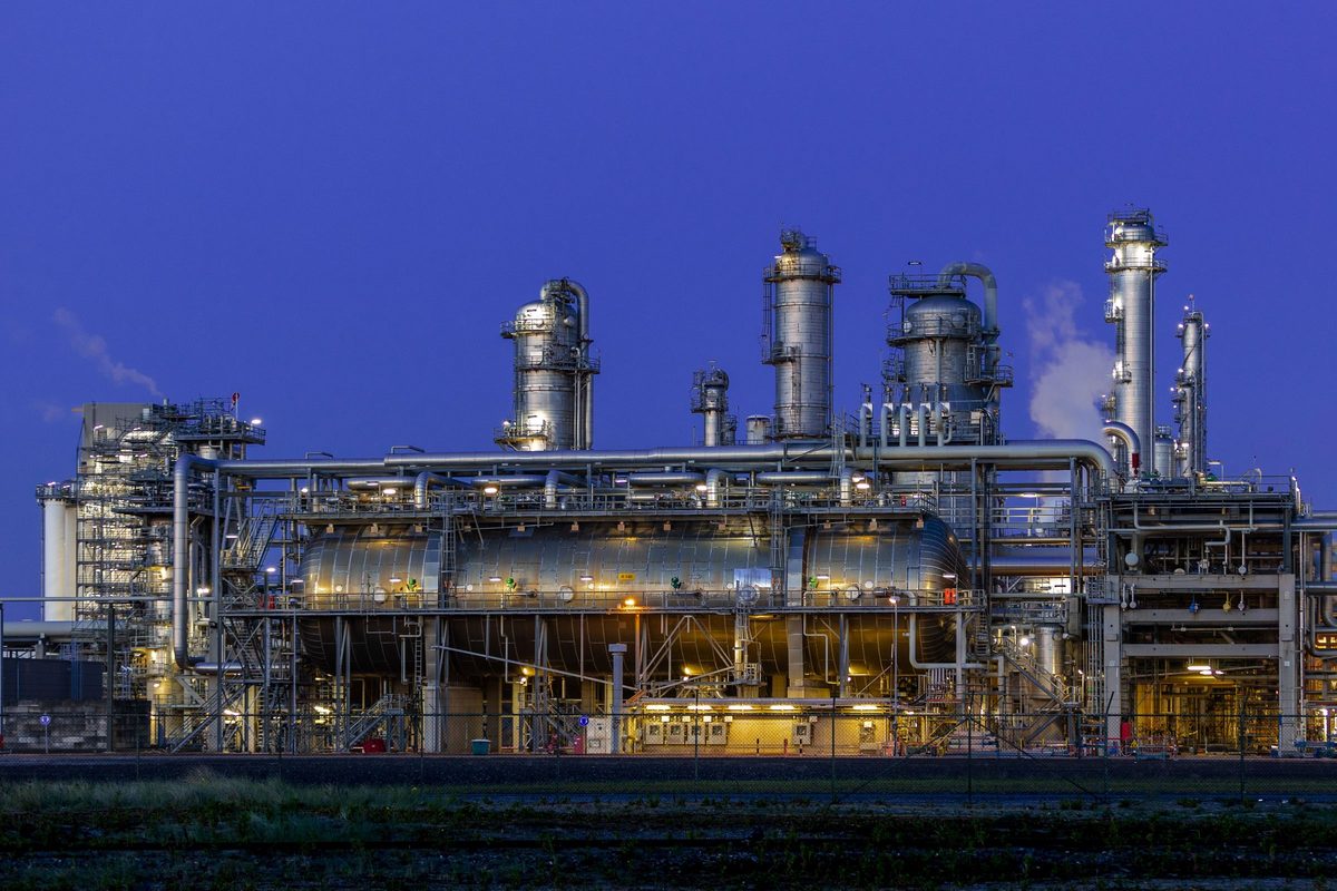
Free expansion causes no stress
Steel grows by a fixed fraction for each degree it is heated. That fraction is the coefficient of thermal expansion α, about 12 × 10⁻⁶ per kelvin for carbon steel. The free thermal strain is:
A 1 m bar heated by 100 K gets 1.2 mm longer. If nothing stops it, every part of it grows by the same fraction, and no part pushes on another. There is strain but no stress. A whole vessel heated evenly is the same: it grows in every direction and stays stress-free.
Full restraint
Now hold both ends of the bar between rigid walls and heat it. It cannot get longer, so the walls must squeeze it back by exactly the free growth. The mechanical strain is −α·ΔT and the stress follows from Hooke's law:
The answer does not depend on the bar's length or its cross-section. A thicker bar is no help: it grows by the same strain and pushes back with a larger force over a larger area. For steel, 100 K of fully restrained heating gives about 240 MPa, close to the yield strength of many carbon steels.
Partial restraint
Real restraint is rarely rigid. A bar held by a support that itself gives a little, modelled as a spring of stiffness k, shares the free growth with the spring. The bar's own axial stiffness is E·A/L, and the stress is:
When the support is much softer than the bar, r is small and so is the stress. When it is much stiffer, the stress approaches the fully restrained value. Equal stiffnesses give half of it.
A temperature difference through the wall
A wall can restrain itself. When the inside of a vessel runs hotter than the outside, the inner layers want to grow more than the outer ones. In a long cylinder, far from its ends, the layers cannot slide past each other and the ring must stay round, so the hot side is pushed into compression and the cold side pulled into tension. For a temperature that changes linearly through the wall by ΔT:
The stress is a pure bending distribution through the wall: it adds no net force and no net moment to the section. If the temperature through the wall is curved rather than straight, as it is during a fast start-up, the curved part of the stress is self-balancing too and counts as peak stress. Near a free end, a head or a change of thickness the pattern changes and the stress there can be somewhat higher.
Why it is judged by its range
Thermal stress comes from a fixed amount of strain that has to be absorbed. If the metal yields a little, the strain is absorbed and the stress stops rising. It limits itself. That is the mark of a secondary stress, and design rules treat it so: the thermal stress is added to the primary stress, and the range of the sum between the coldest and hottest states is compared with a typical limit of about 3 times the allowable stress. The curved through-wall part goes into the fatigue check as peak stress.
Two cautions. When a stiff part drives a much softer one, the softer part can take far more than its share of the strain, a case called elastic follow-up. And thermal cycling on top of steady pressure can make strain grow cycle by cycle, which is ratcheting. The exact rules are code-specific, so check your governing code.
Where it shows up at attachments
- A nozzle with a hot connected line: the line grows and pushes on the nozzle, so the forces and moments at the nozzle are partly caused by restrained expansion.
- Clips, rings and supports that run cooler than the shell they are welded to, so the shell is held back where they join it.
- The skirt-to-head junction of a hot vertical vessel, where the temperature falls along the skirt.
- Thick nozzle forgings and flanges that lag behind a thin shell during start-up and shut-down.
Key points
- Free thermal expansion α·ΔT causes strain but no stress.
- Full restraint gives σ = −E·α·ΔT, whatever the length or the size of the section.
- Partial restraint gives a share r/(1 + r) of that, with r the support's stiffness over the part's.
- A linear temperature difference through a long cylinder's wall gives ± E·α·ΔT/(2(1 − ν)) at the faces.
- Thermal stress limits itself, so it is classed as secondary or peak and judged by its range.
Where this matters in practice
- Nozzle loads from hot connected lines, which come from restrained growth rather than weight.
- Clips and stiffening rings at a different temperature from the shell.
- Skirt-to-head junctions of hot columns and reactors.
- Start-up and shut-down of thick-walled vessels, where the through-wall difference is largest.
- Vessels in cyclic service, where the thermal range feeds the fatigue and ratcheting checks.
FEXLA checks the local stress at a nozzle or clip from the forces and moments you enter at the attachment, and shows each step of the working.
See the nozzle checkRelated principles
- Load-controlled and displacement-controlled loadsLoads that must be carried, movements that balance themselves, and why yielding helps only one of them.6 min read
- Ratcheting and the Bree diagramThe classic cylinder behind the Bree diagram, region by region, and how its boundaries became design limits.7 min read
- Ratcheting and shakedownWhat happens when a steady stress meets one that cycles: shakedown, plastic cycling or ratcheting.6 min read
Next principle: Ratcheting and the Bree diagram
Educational article. It explains principles and is not design guidance; follow your governing code and edition.