The bending moment from an agitator shaft turns with the shaft, so at any fixed point of the nozzle it swings from plus to minus once every revolution. Over a design life that is hundreds of millions of cycles, with a stress range of twice the vendor's moment. That makes the welds of the nozzle a fatigue problem, and a nozzle can pass every static stress check while its weld fatigue fails.
This post goes through the range, the count and the fatigue check at the welds.
The range: twice the moment
The vendor gives a shaft bending moment at the mounting flange. For a static check it is one load. For fatigue the point is that it rotates. A point on the nozzle wall sees the moment's full value on one side of the shaft, and its full value of opposite sign half a turn later. The agitator job builds a fatigue event that swings the bending between minus and plus the vendor's moment at operating pressure, so the range is twice the moment.
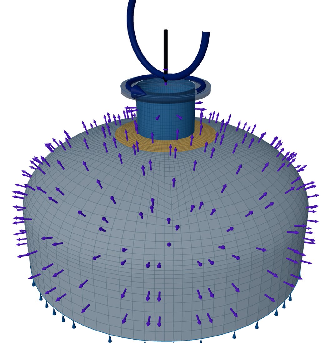
The weight, thrust and torque are steady while the machine runs. They set the mean stress the bending swings about, and they change only at start-up and shutdown, which are counted as a separate event.
The count: one cycle per revolution
At these counts the fatigue screening rules do not apply: above a million significant cycles VIII-2 asks for a fatigue analysis. And the welded joint curves keep falling with cycles, with no endurance limit below which a range does no damage. A small range repeated 10⁸ times still adds up.
Reading the welds
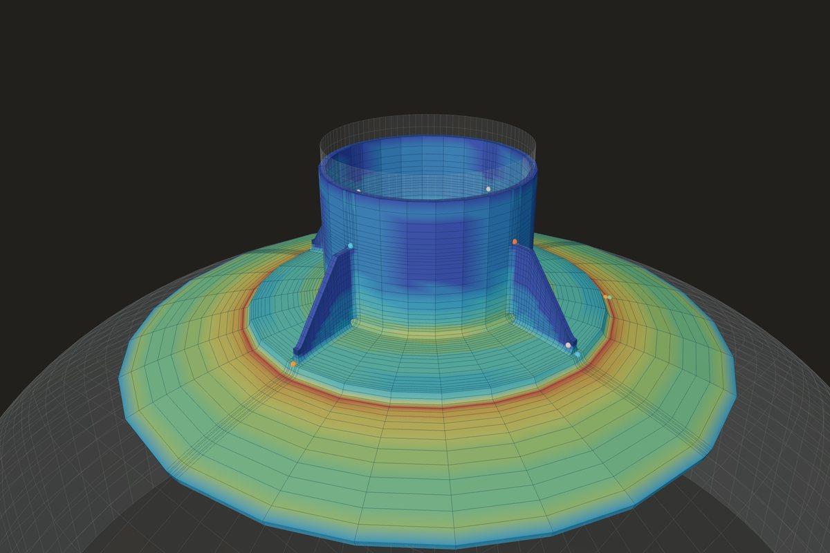
The check runs along each weld line of the model: the nozzle-to-head junction on the head side and the nozzle side, and the pad's outer edge, at every node and on both faces. Each point is a possible crack site. The stress there is the structural stress, from a linearisation across the weld line: membrane and bending normal to the line. Against a solid model of a published example it reads 3 % low in membrane plus bending and does not change with the mesh.
- Method C turns the structural stress range into an equivalent range, with a thickness term for walls between 16 and 150 mm, a bending-ratio term and a mean-stress term, and reads it on the welded joint curve.
- Each event's cycles are counted against that curve, and the damage n/N is summed over the events: rotation and start-ups together.
- A point passes when the damage is at most 1.
The rotation and the start-ups are counted together. At each point the max-min method of VIII-2 Annex 5-B takes the largest range between any two load states first, counts it the smaller number of times the two states occur, and repeats until no range is left.
What the default case shows
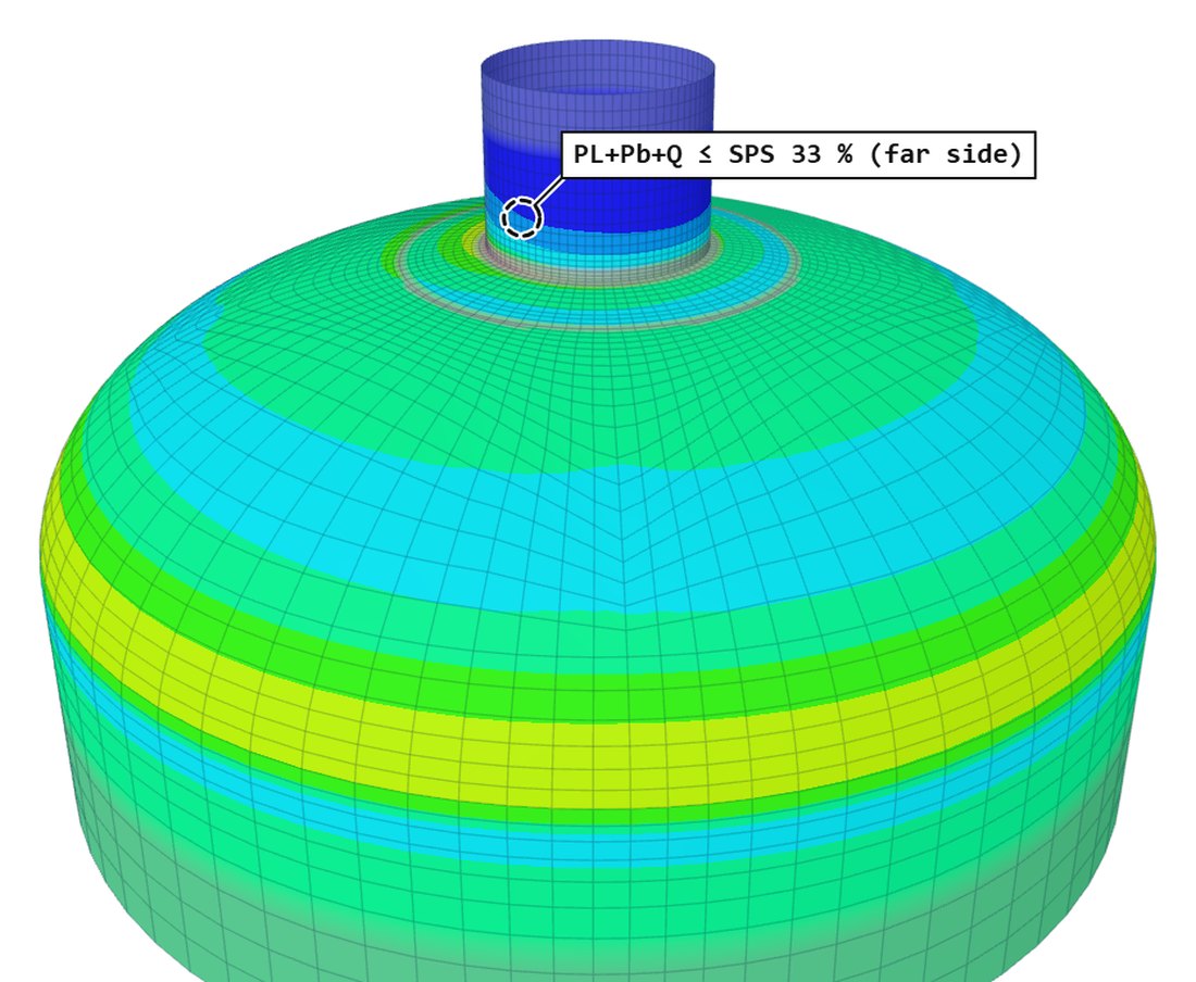
The dev log records the default agitator passing its stress checks at 34 % of the allowable while the welded-joint fatigue fails, with a damage of about 118 at 8.6 × 10⁸ cycles. The static ratio gives no hint of it. The levers are the bending moment itself, from the vendor, and the stiffness round the nozzle: a thicker neck, a pad, or gussets, each changing the range at the weld that governs.
Method A of the fatigue rules, an elastic stress range times a fatigue strength reduction factor read on the smooth-bar curves, is coded as well. For an as-welded joint Method C is the one to use: it is read at the weld line itself and does not depend on a factor chosen for the weld.
Where it stops
- 01One cycle per revolution only: blade-pass harmonics, hydraulic unbalance and resonance are not computed; the vendor's moment must include them.
- 02Loads are static and the flange face is a rigid plane; shaft and gearbox stiffness are not modelled.
- 03Weld misalignment and peaking are not modelled.
- 04Fatigue results are early access and under verification, and are no substitute for the vendor's and the engineer's review.
Try it in FEXLA
The Agitator nozzle card turns the vendor's loads, speed and run hours into load cases and cycle counts, and checks fatigue along every weld line.
Open the cardReferences
- ASME Section VIII Division 2, 5.5 (fatigue): 5.5.4 Method C, the structural stress method, and Annex 3-F (welded joint curves).
- ASME PTB-3, example E5.5.5, for the structural stress comparison.
Method notes this draws on
Next post: Air-cooler plug header ligaments and Appendix 13
Educational article. It explains principles and is not design guidance; follow your governing code and edition.