Blog
50 posts, each one question an engineer asks at the desk, answered from our notes and from what the tools compute.
Filter50 in all
§ 01All posts
50 itemsEach ends with where the method stops and the card that runs it. The method notes and principles are on the Learn page.
- B-01How WRC 537 checks a nozzle, step by stepThe order the calculator works in, from the load table to the pass or fail, and what each step adds.5 min read
- B-02When WRC 537 stops and a shell model is neededThe limits of the bulletin, how the calculator flags each one, and what the shell model does when it takes over.4 min read
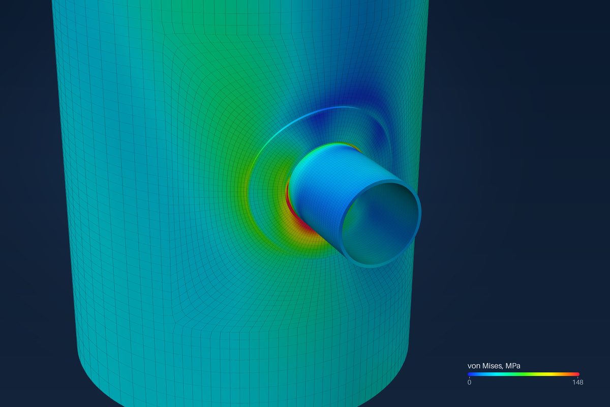 B-03Primary vs secondary stress at a nozzle (VIII-2 Table 5.6)Which part of the stress at a nozzle is primary, which is secondary, and what each one is checked against.4 min read
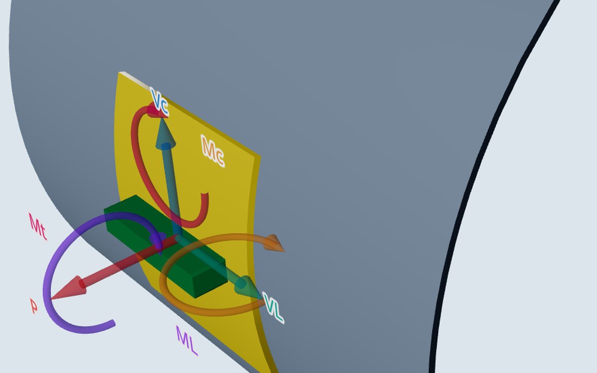 B-04Load sets: design, sustained, operating, occasional — what changes in the checkThe same six numbers checked four ways: which limit each load set meets and which combinations the tools run.5 min read
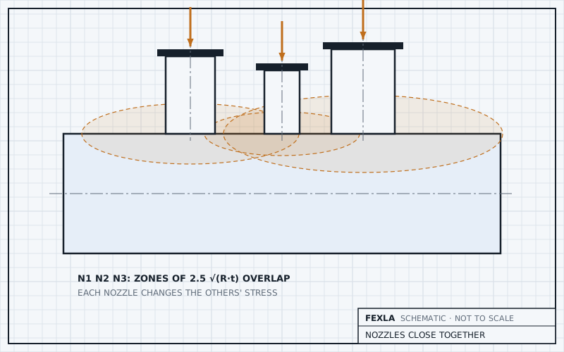 B-05Nozzles close togetherHow close is close, why separate checks miss the interaction, and what the shell model does about it.4 min read
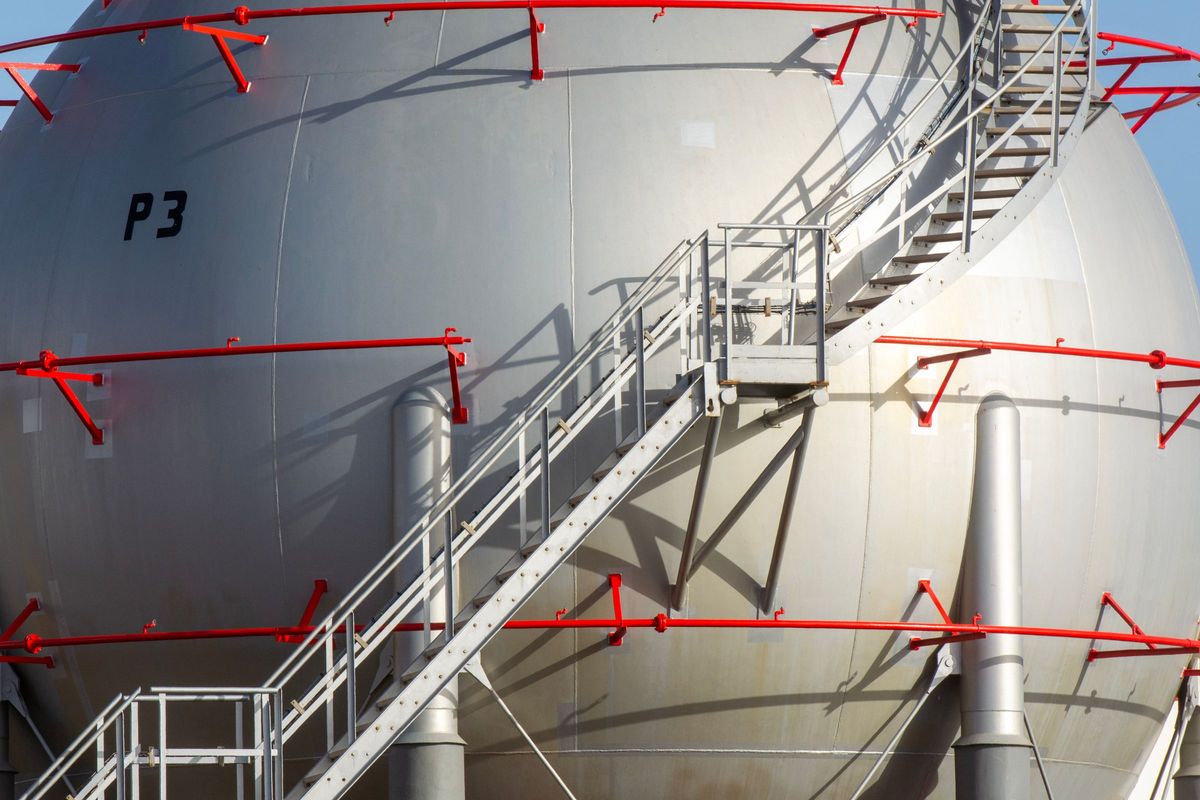 B-06Clips and platform supports: entering a footprintThe rectangle WRC 537 needs, how a rolled section becomes one, and what the clip check leaves out.4 min read
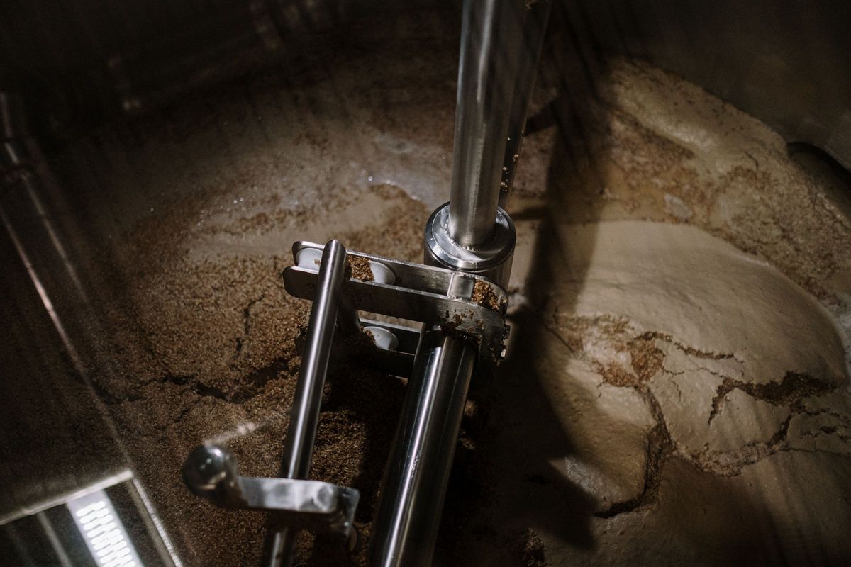 B-07Agitator nozzles: loads, gussets and fatigueWhy the rotating bending moment, not the stress ratio, usually decides an agitator nozzle.4 min read
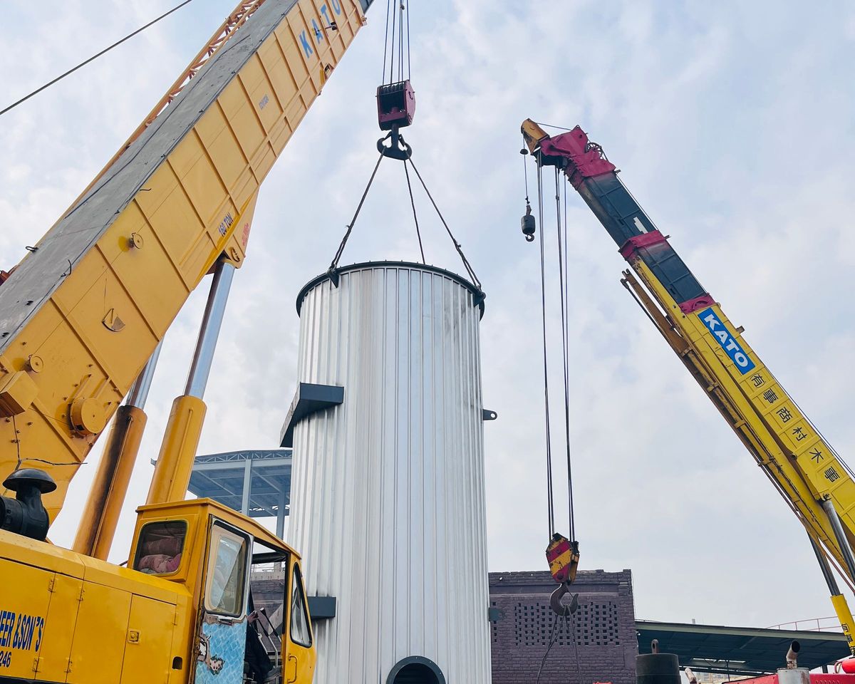 B-08Lifting lug checks by Moss and AISCFrom the lift angles to the pin hole: the statics, the factored load and each check on the lug plate.5 min read
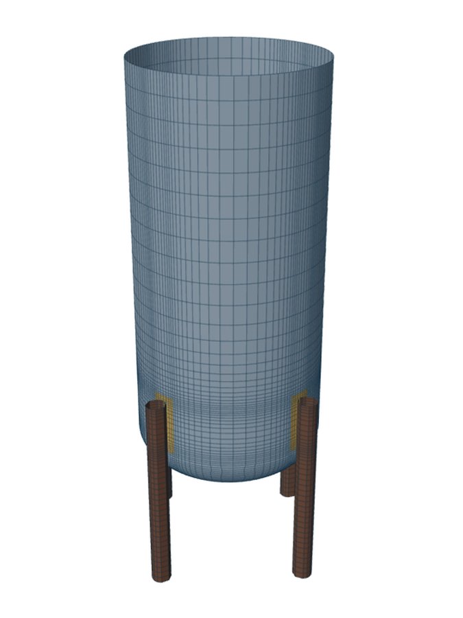 B-09Vessel on legs: Moss Chapter 4 checksFrom the overturning moment to the anchor bolts: the hand checks for legs, and the shell at each leg.4 min read
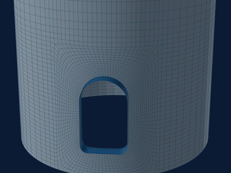 B-10Skirt access openings and bucklingWhy the wall beside a skirt opening is the weak point, the two hand checks, and the buckling check of the model.4 min read
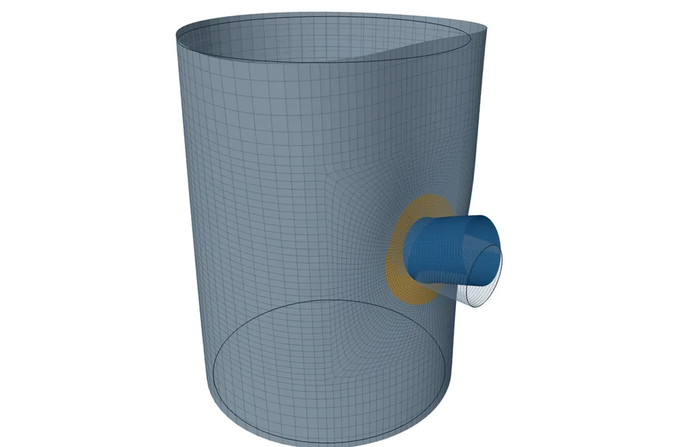 B-11Limit load (VIII-2 5.2.3) when the elastic check failsWhat a limit-load analysis solves, which combinations it runs, what a pass replaces and what it does not.4 min read
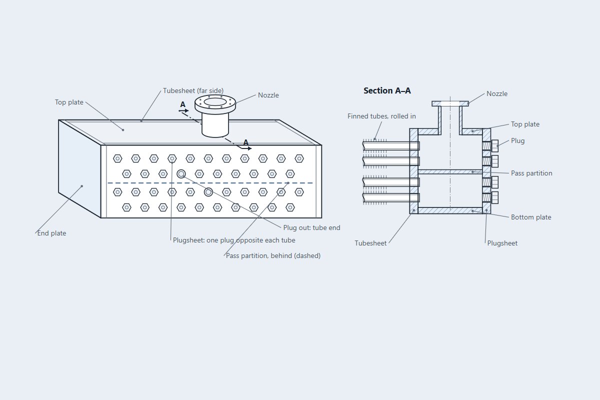 B-12API 661 plug headers to Appendix 13Why a box header bends where a cylinder would not, and how Appendix 13 checks it location by location.4 min read
- B-13WRC 537 or a shell model for a nozzle: how to chooseStart with WRC 537, read what it flags, and move to the shell model only when the flag or the job calls for it.5 min read
 B-14WRC 107, WRC 297 and WRC 537: what changed, and what FEXLA usesOne theory, published first as charts and later as equations; what FEXLA takes from WRC 537 and what it leaves out.4 min read
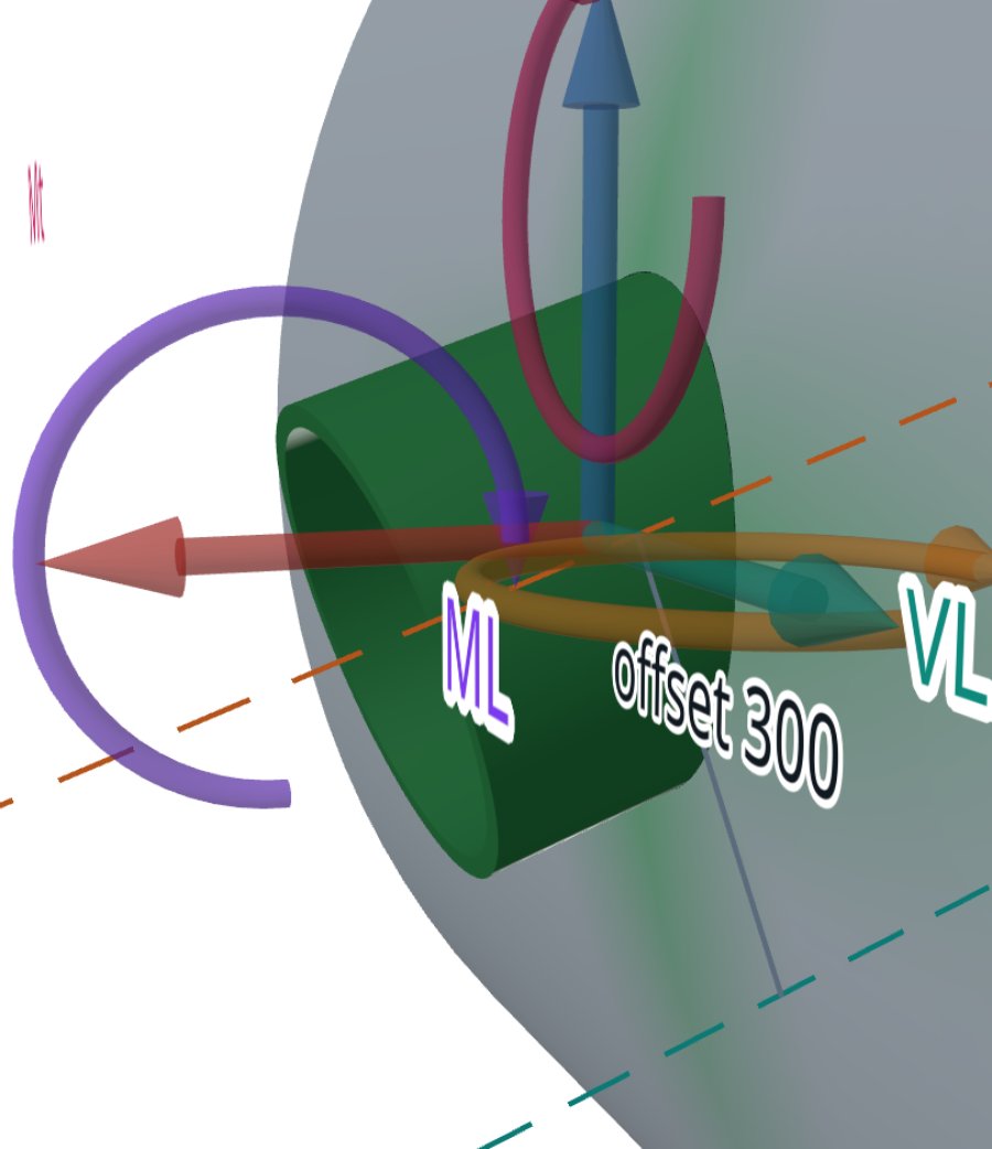 B-15The six nozzle load components P, VC, VL, MC, ML, MT and their signsAxes, positive senses and the stress each of the six loads puts at A, B, C and D, as the calculator computes it.5 min read
- B-16How a reinforcing pad changes nozzle stress under external loadsA pad moves the problem rather than removing it: two edges to check, and the load still has to pass through the nozzle.5 min read
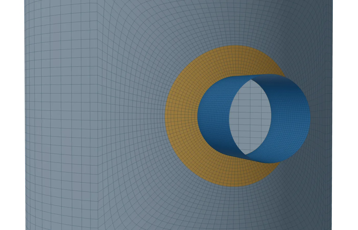 B-17Hillside and tangential nozzles: what WRC 537 coversA hillside nozzle stays in the bulletin with a larger pressure factor; a tangential or tilted one goes to the shell model.4 min read
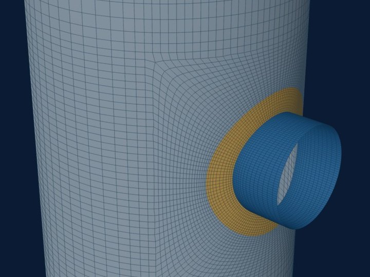 B-18Large openings beyond UG-36(b): why the rules stop and what replaces themBoth the opening rules and the bulletin assume a small hole in a large shell. Past that, the shell model of the real geometry takes over.5 min read
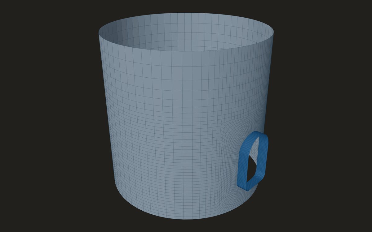 B-19Obround and tombstone openings: how they are analysedThe bulletin never charted a non-round opening. The shell model builds the real outline and finds where the stress gathers.5 min read
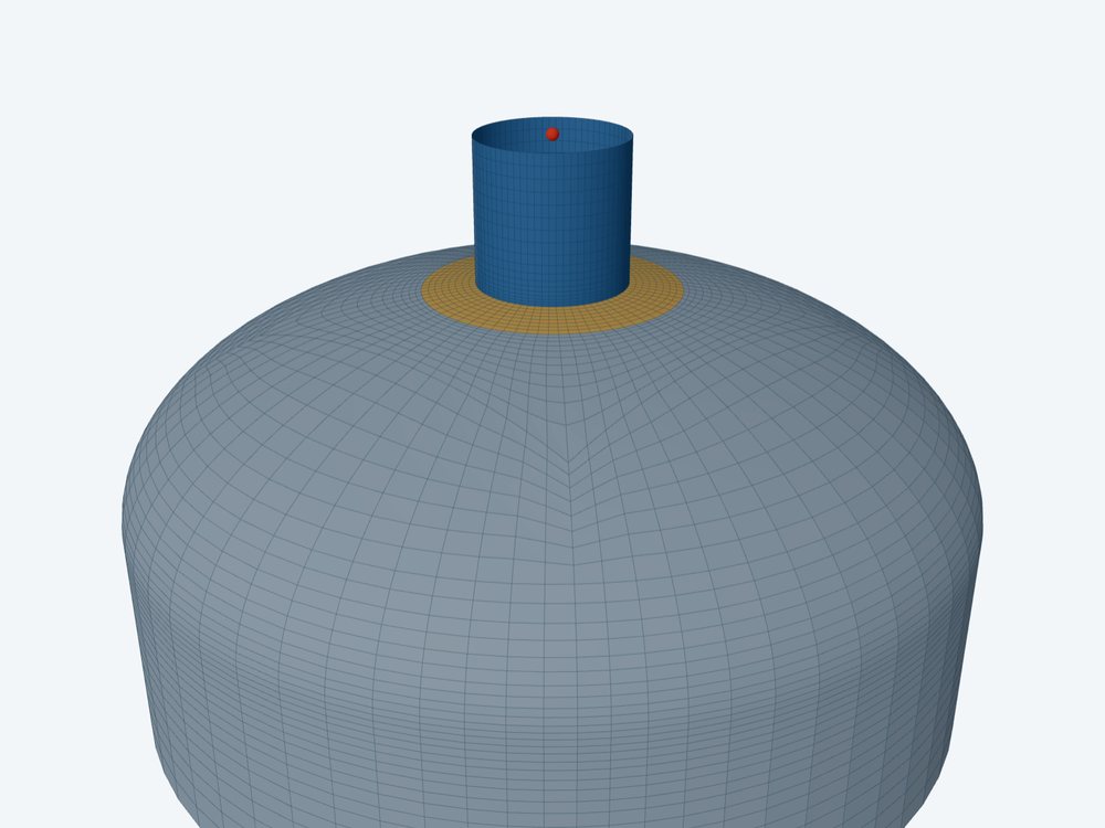 B-20Nozzles on formed heads: the spherical region, the knuckle and WRC 537WRC 537 treats a head as a sphere, which is true only in its spherical region. Near or on the knuckle, the shell model takes over.5 min read
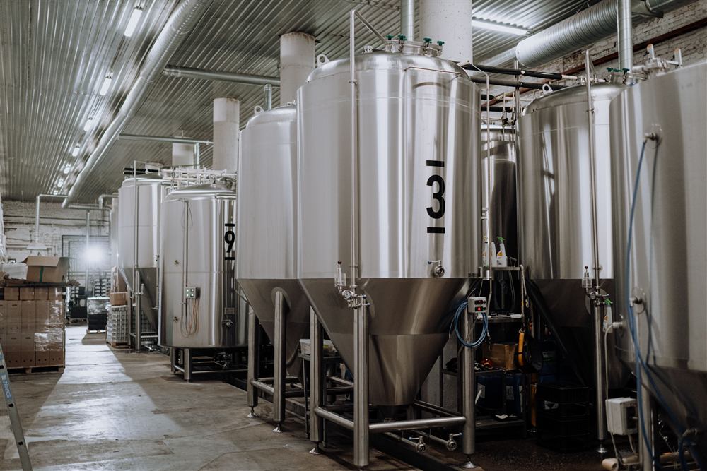 B-21How WRC 537 handles a nozzle on a coneThe equivalent cylinder at the local cone radius, where the cone angle still enters, and when the shell model is the better answer.5 min read
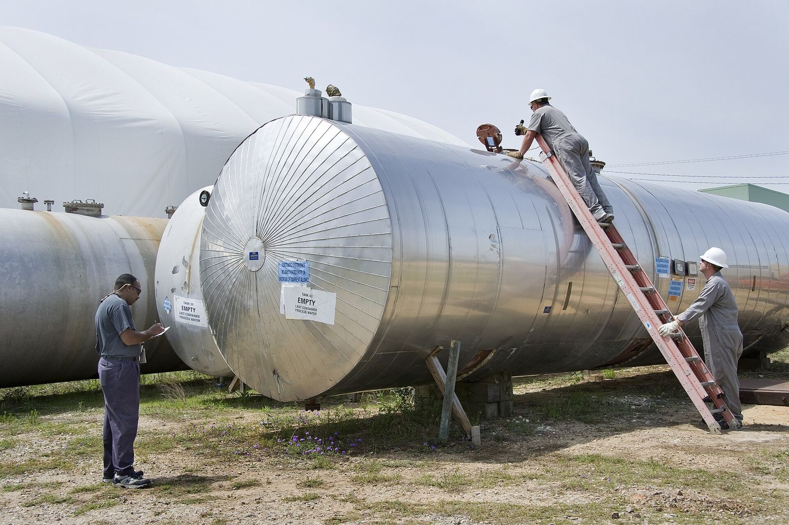 B-22Nozzle loads on a flat head or a flat plateWhy the bulletin cannot be used, what the shell model of a flat plate holds at its edge, and which limits apply where.4 min read
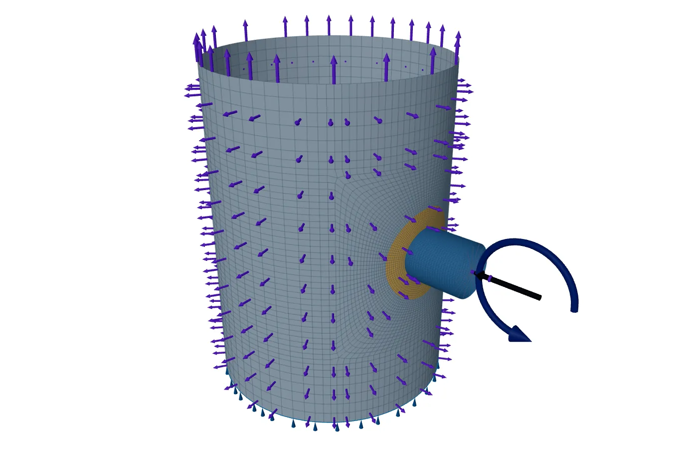 B-23Load envelopes: nozzle loads with unknown signsA set acts together with known signs; an envelope does not. How to check an envelope, and what to do when it fails.5 min read
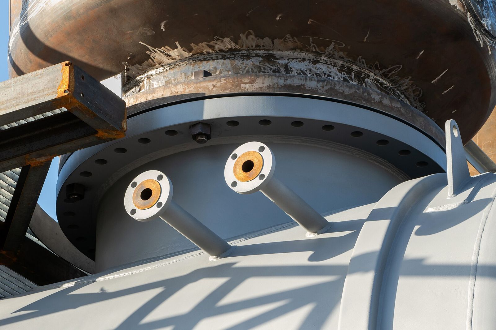 B-24Using nozzle load tables by nozzle size and flange ratingEnter the standard table once, pick a row by size and class, and check it as the envelope it is.5 min read
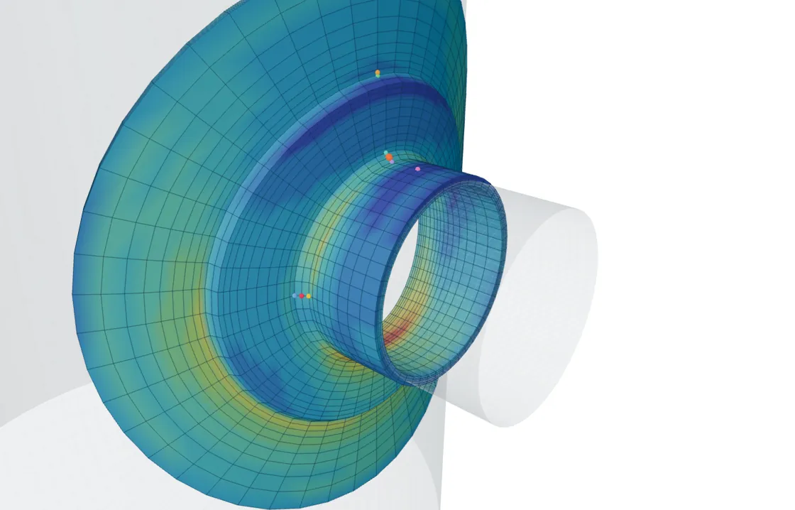 B-25Weld-toe stress in a shell model: where it is read and what it missesThe intersection line, the weld toe and the weld zone between, and what a shell model can and cannot say about the toe.5 min read
- B-26Where to place a stress classification line at a nozzleThrough the wall, normal to the mid-surface, at each discontinuity and clear of sharp corners: how to place the line.6 min read
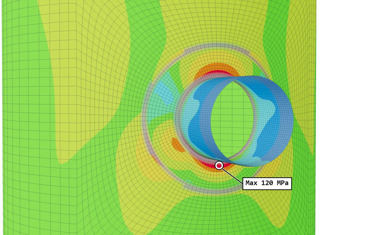 B-27Stress linearisation by Annex 5-A, with a worked exampleMembrane is the average, bending comes from the first moment, peak is the rest: one line worked by hand.5 min read
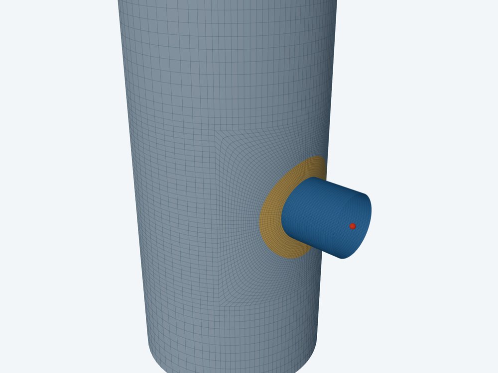 B-28The local primary membrane region test (VIII-2 5.2.2.2(b))How far local membrane stress may spread before it counts as general, and how much of that FEXLA checks today.4 min read
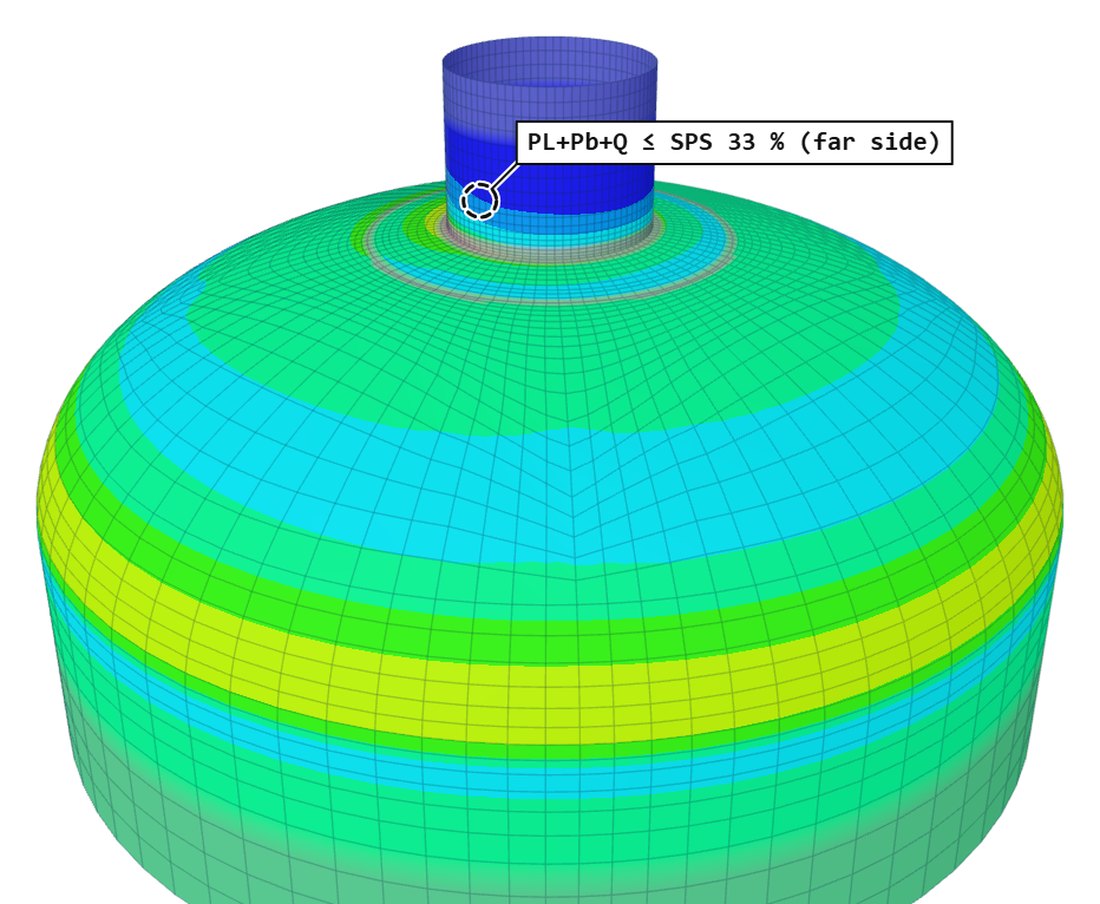 B-29The primary plus secondary stress range limit, SPSThe range check on primary plus secondary stress: what SPS is, how FEXLA sets it, and what runs when it fails.4 min read
- B-30Why every nozzle check is also run with the pressure offPressure tension can cancel load compression, so the load alone can govern. The cases FEXLA runs with pressure at zero.5 min read
- B-31How long should the shell be around a nozzleA drinks can, two programs and one rule: model the shell out to the real heads and rings, or 50√(R·t) each side when they are not known.6 min read
- B-32Corrosion allowance in a local model: inside, outside, pads and clipsWhich faces lose metal, what that does to the mid-surface, and when the uncorroded vessel is the worse case.4 min read
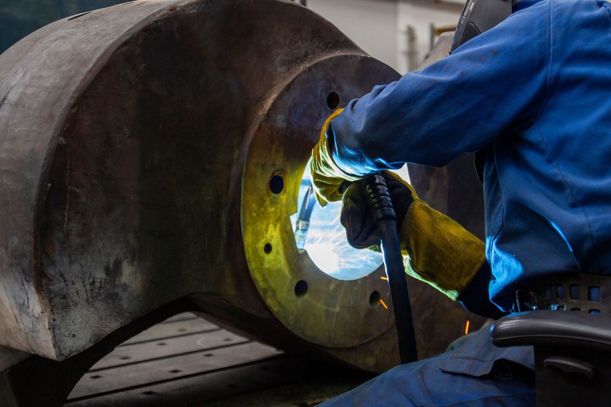 B-33Shell courses and thickness steps with UW-9(c) tapersCourses, seams, the 3:1 taper and the small step below the trigger: what each does to the stress at an attachment.4 min read
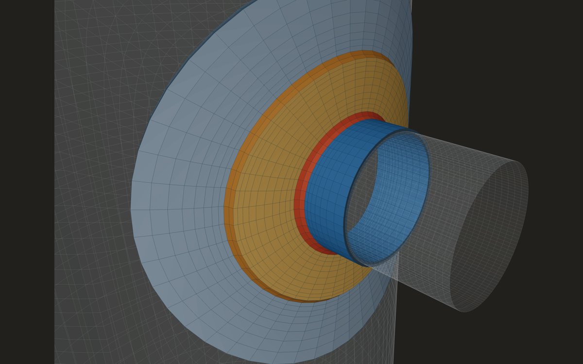 B-34Insert plates round a nozzle: how a local model takes themA thicker plate let into the shell: its taper, the second discontinuity at its edge, and what the model credits.4 min read
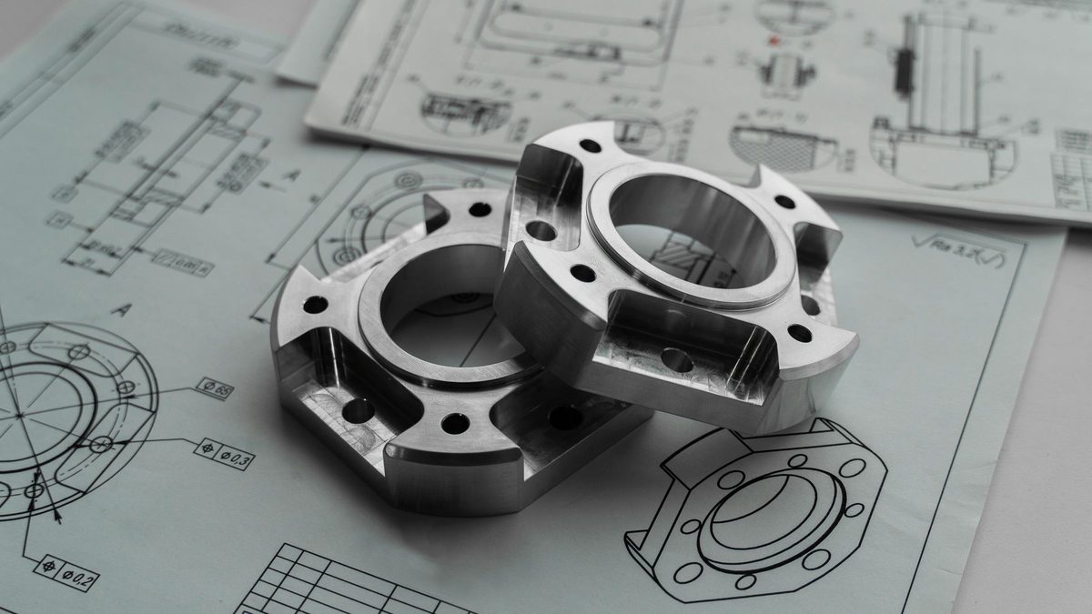 B-35Q-lip, forged and long weld neck nozzles in a local modelThree heavy nozzle styles as a shell model sees them: the lip, the hub and taper, the forged profile and the long neck.4 min read
- B-36Angle and channel clips entered by footprintMoss's factors for angles and channels, the placement they assume, and the leg directions the shell model asks for.4 min read
 B-37Platform and ladder clips: the loads and what is checkedFrom the platform's reactions to the six loads at the clip, and the parts of the check that stay with the steelwork.4 min read
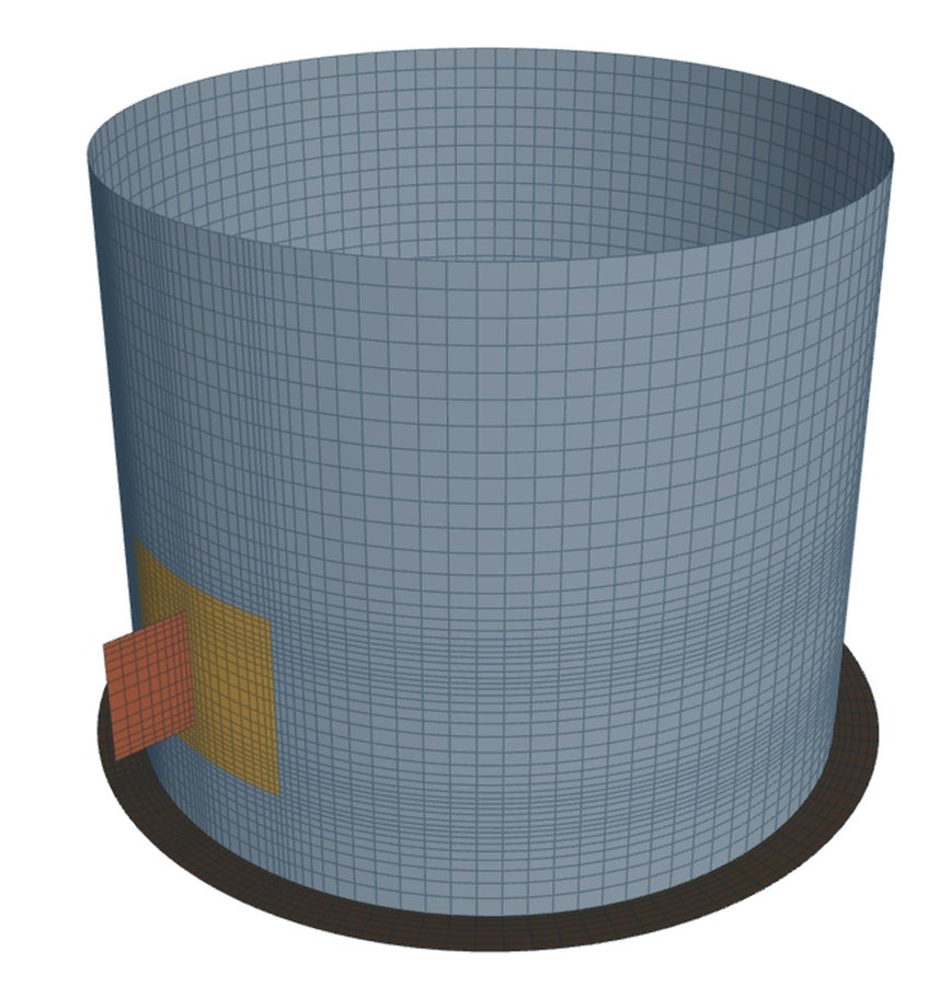 B-38Trunnions against plate lugs: what each check coversThe pin hole against the beam: the checks on a plate lug and a trunnion, and how each loads the shell.4 min read
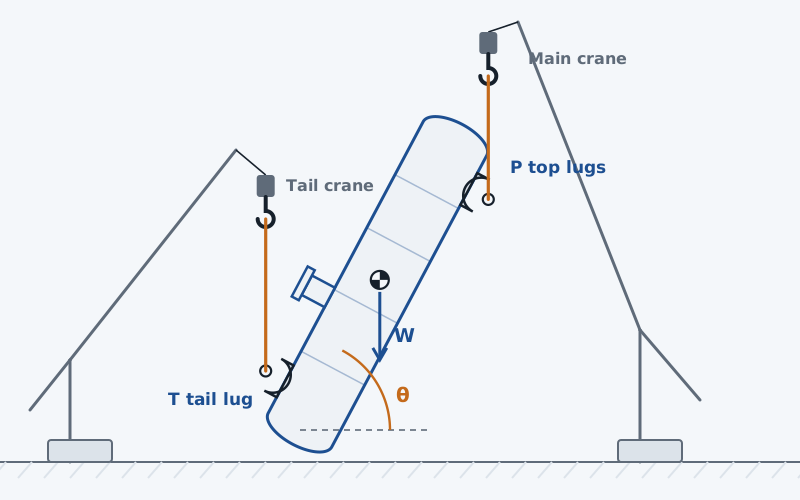 B-39A tailing lug with a base ring, a compression ring or a strutThe base ring under the tail load by Moss 10-5, the struts that stiffen it, and the ring arrangements the model meshes.4 min read
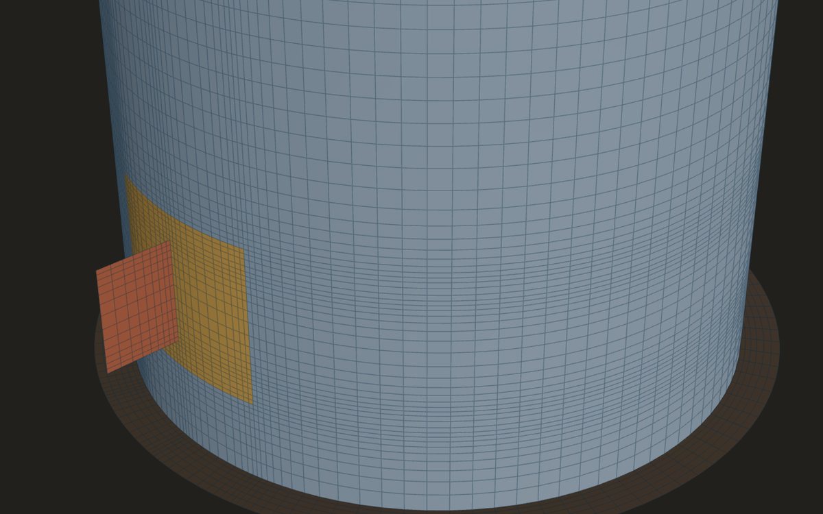 B-40Lifting a vertical vessel: the Moss lift stepsFrom horizontal to vertical in steps: moments about the tail pin, the two loads, and the angles that need a warning.4 min read
 B-41Shackle selection and the pin-hole fit on a lifting lugThe rating is the maker's. What the lug check adds: the load it is compared on, and four fits of shackle to lug.4 min read
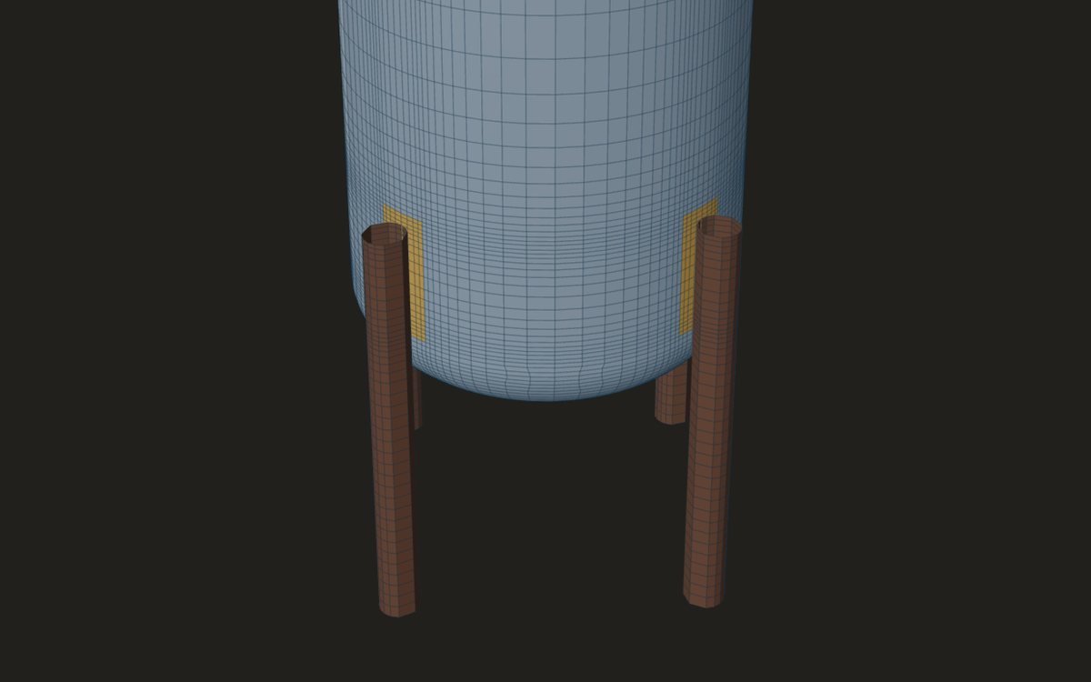 B-42A vessel on legs: the leg-to-shell check by WRC 537From the Moss leg loads to the WRC 537 rows: the two legs checked, the moments at the weld, and the footprint used.4 min read
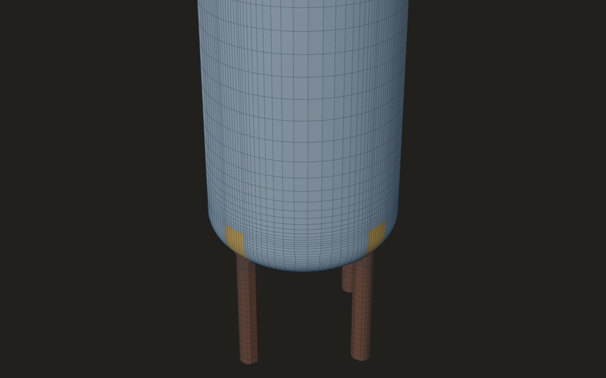 B-43Legs at the shell-to-cone junctionA leg welded across the junction: two discontinuities at once, why the bulletin stops, and what the model meshes.4 min read
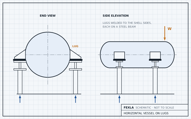 B-44A horizontal vessel on four support lugs: the load shareStatics gives part of the answer. The shell's stiffness gives the rest, so the whole vessel is modelled on its lugs, and the lug itself is sized by hand.6 min read
- B-45Skirt access openings: tombstone against obroundSame width, different corners: what the shape changes at a skirt opening, and what the hand check cannot see.4 min read
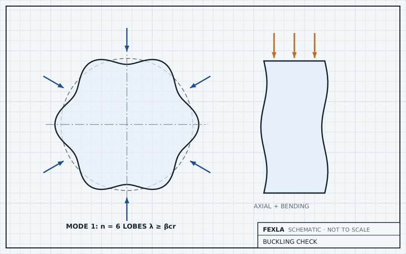 B-46Skirt buckling under weight and wind, with the design factorsFrom the foundation loads to a buckling verdict: which factors go where, and why a large load factor can still fail.4 min read
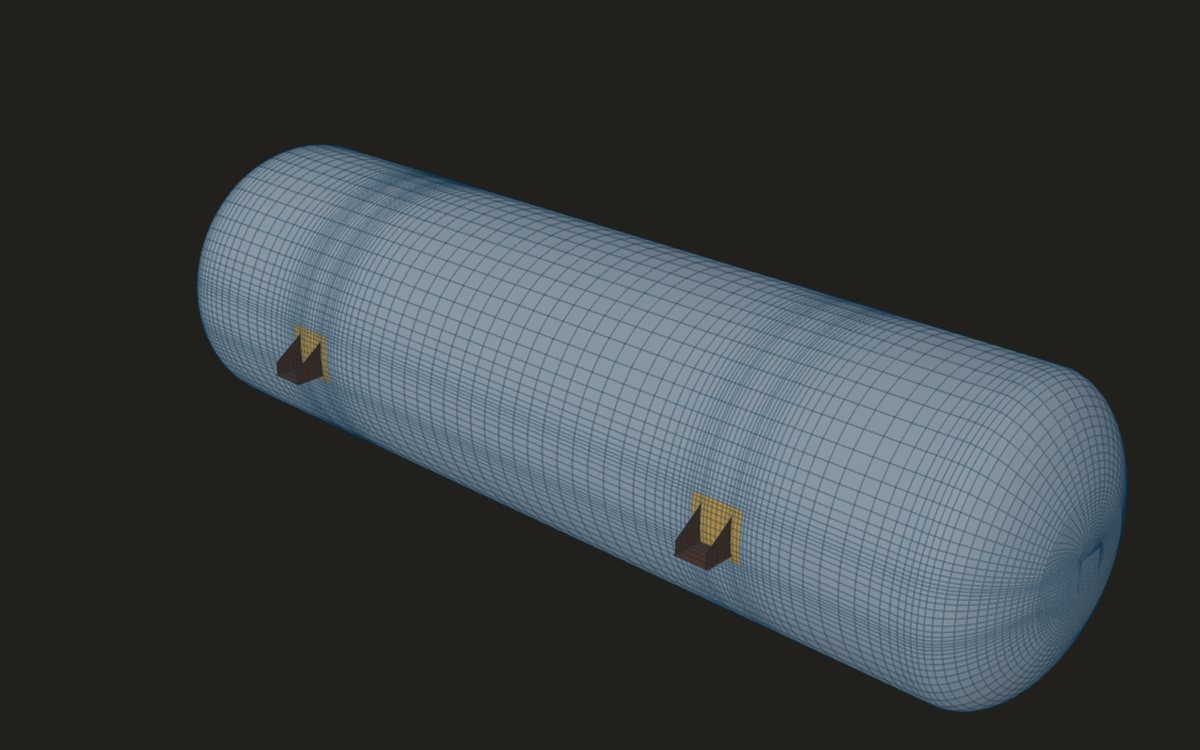 B-47Vacuum vessels with attachments: what changesUnder vacuum the shell can buckle as well as overstress. What that changes in the model, the loads and the verdict.4 min read
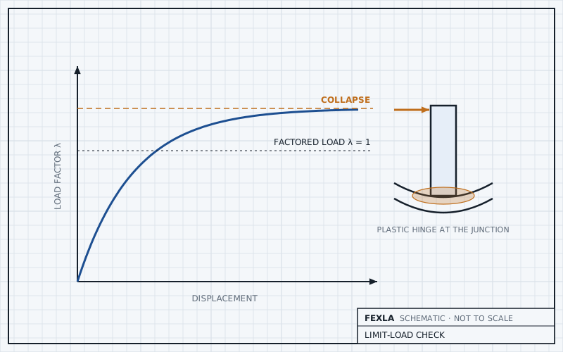 B-48Limit load against the elastic check: rescuing a failing nozzleWhich failing rows a limit-load pass replaces, which checks stay, and what to watch in the model before trusting it.4 min read
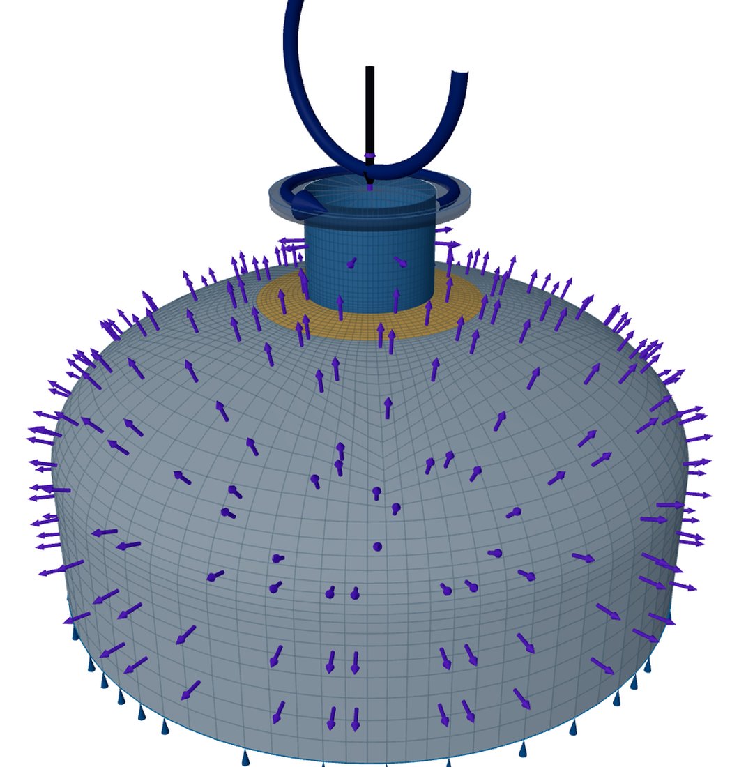 B-49Agitator nozzle fatigue from rotating bendingA moment that turns with the shaft: how it becomes a stress range, a cycle count and a damage sum at the nozzle welds.4 min read
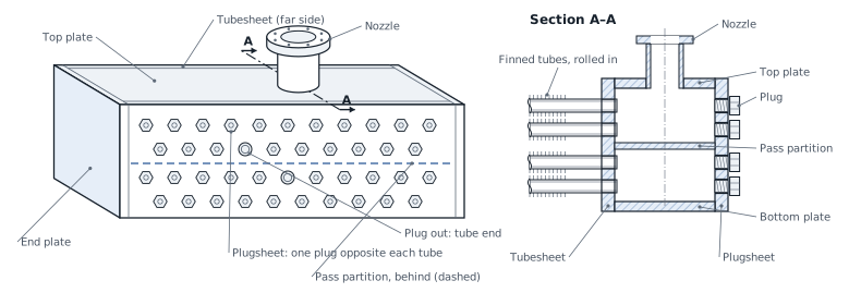 B-50Air-cooler plug header ligaments and Appendix 13Rows of stepped holes through a plate: two efficiencies, one for membrane and one for bending, and how they enter the check.4 min read
Educational article. It explains principles and is not design guidance; follow your governing code and edition. The finite-element tools are free during early access and under independent verification before design use.