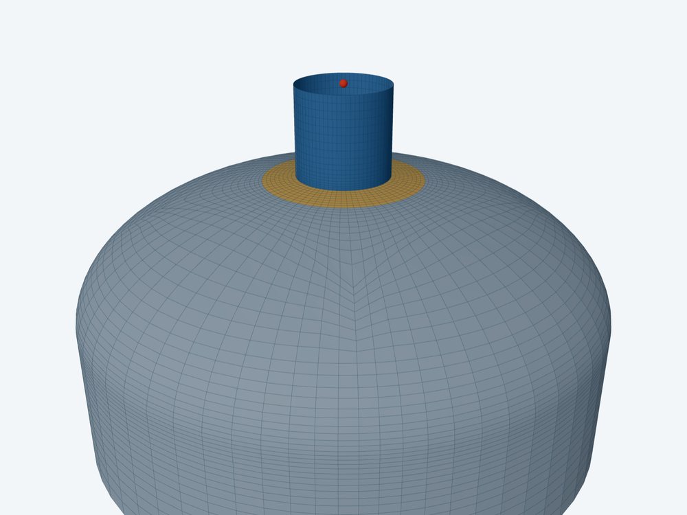
WRC 537 checks a nozzle on a formed head as a nozzle on a sphere of one radius. That holds only in the head's spherical region: the crown of a torispherical head, the central 0.8·D of a 2:1 ellipsoidal head, or the whole of a hemispherical head. A nozzle that reaches the knuckle needs a shell model of the real head.
This post covers the radius the calculator uses, how it finds the edge of the spherical region, the size limit of the sphere theory, and what the shell model does with a knuckle.
Which sphere
The bulletin's sphere method needs one mean radius Rm. For each head type the calculator takes it from the head as drawn:
- Ellipsoidal: Rm = K1·D + t/2, with K1 from Table UG-37 by the ratio D/2h. K1 is 0.90 for a 2:1 head.
- Torispherical: Rm = L + t/2, with L the inside crown radius.
- Hemispherical: Rm = D/2 + t/2.
The head's proportions are checked first, and a head outside them is refused. An ellipsoidal head must have D/2h between 1.0 and 3.0. A torispherical head must have L no more than the outside diameter, a knuckle radius r of at least 6 % of the outside diameter and at least three times the thickness, and L/r between 1 and 16⅔.
Where the spherical region ends
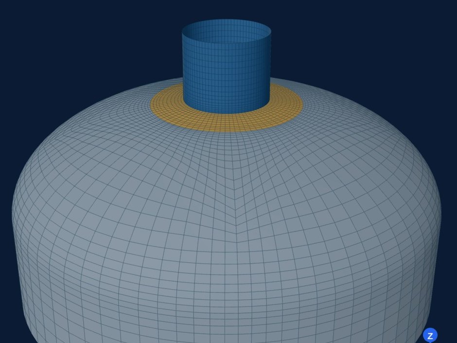
With the head described in full, the calculator works out the radius from the head axis at which the spherical region ends. On an ellipsoidal head it is 0.4·D. On a torispherical head it is the point where the crown meets the knuckle, ρ = L·(D/2 − r)/(L − r). On a hemispherical head it is D/2.
The attachment is then placed by the distance from the head axis to the nozzle centreline. Its reach is that distance plus the outer radius of the pad, or of the nozzle when there is no pad. If the reach passes the edge of the spherical region, the result says WRC 537 does not apply there. Without the head described, the result asks the engineer to confirm the position by hand.
How large a nozzle the sphere theory takes
The sphere curves rest on shallow-shell theory. The bulletin limits the ratio of nozzle mean diameter to shell mean diameter, dm/Dm, to about one third for a thin shell. For a thicker shell, Dm/T between 20 and 55, the limit is lower, about 0.17 at Dm/T of 20, read from the bulletin's figure. Below Dm/T of 20 the method is outside its limits altogether. The calculator works out the limit for the head's own Dm/T and advises a shell model past it.
Note that Dm is the diameter of the equivalent sphere, not of the head. On the 2:1 head above Dm is 3620 mm, so the one-third limit is a nozzle of about 1200 mm mean diameter. Off the pole, the spherical region usually limits the nozzle first.
Pressure adds its own term. The calculator works the pressure stress intensity factor of ASME Section VIII Division 2 for a nozzle in a formed head, radial or non-radial, when the head type, diameter, depth and nozzle position are given. Without them the factor is 1 and the result warns that the local pressure stress is likely understated.
Why the knuckle is different
The knuckle joins two shapes. Along the meridian the radius of curvature jumps from the crown radius L to the knuckle radius r, which may be a tenth of it or less. Under pressure that change of shape is a discontinuity of its own, with bending in the wall even before a nozzle is added. WRC 537 knows one radius and no discontinuity, so it has nothing to say about a nozzle there.
The shell model builds the head in its true shape: hemispherical, ellipsoidal by its D/2h, or torispherical by its crown and knuckle radii. Element rows along the meridian are kept no longer than a tenth of the local meridional radius, so they shorten through the knuckle where the curvature is tight. A nozzle on the knuckle can be modelled when it is the only attachment on the head. Several attachments must stay on the crown, and no footprint, pad included, may cross the tangent line into the straight flange.
Where it stops
- 01The calculator takes round nozzles only on a head; clips on a head, and clips offset on a head, go to the shell model.
- 02The spherical-region check needs the head type, diameter and nozzle position; without them the position is for the engineer to confirm.
- 03Opening reinforcement for pressure is not sized here; take it from your vessel program.
- 04In the shell model only one attachment may sit on a knuckle, and none may cross the tangent line.
- 05The finite-element results are early access and under verification. Until that is finished they are not a source of design values.
Try it in FEXLA
The Nozzle loads card checks a round nozzle in a head's spherical region by WRC 537, and opens the shell model of the real head for the rest.
Open the cardReferences
- WRC Bulletin 537, Appendix A.2 and Figure A-1 (limits of the sphere method).
- ASME Section VIII Division 1, UG-32, UG-37 (Table UG-37, factor K1) and Mandatory Appendix 1-4.
- ASME Section VIII Division 2, 4.5.10 and 4.5.11 (nozzles in formed heads).
Method notes this draws on
Next post: How WRC 537 handles a nozzle on a cone
Educational article. It explains principles and is not design guidance; follow your governing code and edition.