WRC 537 has no curves for a conical shell. The calculator treats a nozzle on a cone as a nozzle on a cylinder whose diameter is the cone's inside diameter where the nozzle centreline meets it, and marks the result approximate. The cone angle enters only the pressure part of the check; the stresses from the nozzle loads come from the cylinder curves unchanged.
That is a fair answer for a small radial nozzle well away from the cone's ends. It is a weak one for a large nozzle, a steep cone, or a nozzle near a cone junction.
The equivalent cylinder
The cone can be entered as it appears on a drawing: the inside diameters at the large and small ends, the axial length between them, and the axial distance from the large end to the point where the nozzle centreline meets the inside surface. From those the calculator finds the half-apex angle and the local inside diameter. The inside diameter changes linearly along the axis.
From there the work is the cylinder check: the mean radius Rm from the local inside radius and the corroded thickness, γ and β from Rm, the curve coefficients, the stresses at the eight points, and the limits 1.5S and 3S. Nothing in the load stresses knows the shell is a cone.
Where the cone angle still counts
The pressure stress at the opening is not taken from the cylinder. The Division 2 pressure check at the opening has a conical-shell form, and the calculator uses it with the half-apex angle and the direction of the nozzle axis. Three directions are accepted: normal to the cone surface, perpendicular to the vessel axis, or parallel to it. The axis changes the size of the opening in the cone and so the pressure stress; it does not change the load stresses.
Anything else is refused with a reason. An offset or freely tilted nozzle on a cone is outside WRC 537, and so is a clip on a cone; the calculator says to use the shell model for them.
What the equivalent cylinder misses
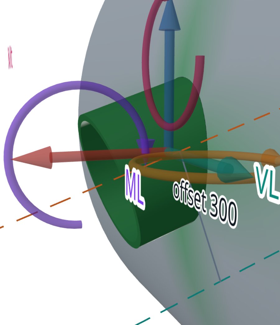
The cylinder curves were drawn for a shell whose radius does not change. On a cone it changes across the nozzle's own footprint: in the illustration above by about 6 % either side of the value used. The larger the nozzle against the local radius, and the steeper the cone, the larger that spread, and the less one radius stands for the shell round the nozzle.
The meridian of a cone is also inclined to the vessel axis, so the membrane forces under pressure differ from those in a cylinder of the same local radius. The calculator does not try to correct for this. It states the approximation on every cone result instead of hiding it.
Nozzles near a cone junction
A cone meets a cylinder or a head at a junction where the shell changes direction. That junction carries bending of its own under pressure, and the bending dies out over a few decay lengths √(Rm·T). A nozzle inside that zone is not alone: the junction stiffens one side of it and adds its own stresses. WRC 537 assumes neither.
The note printed with every cone result says not to use it near a cone-to-cylinder or cone-to-head junction. The calculator does not measure that distance from the cone geometry. If the distance to the nearer end is typed in, it is checked against the same 0.5·Rm limit as on a cylinder, which is a much shorter distance than the junction's bending zone. In the illustration 2.5·√(Rm·T) is about 235 mm from the edge of the nozzle or its pad.
The shell model of a cone
The shell model meshes the cone itself, so the changing radius and the inclined meridian are in the geometry, not approximated. The cone is given by its two end diameters, axial length and thickness. A half-apex angle above 75° is refused as too flat for a cone, and a cone that closes to an apex is not supported.
- Nozzles on the cone body: radial, offset, tilted and tangential, and up to four attachments together, refused when too close.
- A nozzle on the small end, coaxial with the cone, meshed into the cone's end row.
- Clips and other structural attachments on the cone.
- The large end is the support: held along the meridian and round the circumference, its rotation left free, because a cone's meridian rotates under pressure. The small end is free and closed, and carries the closing thrust.
The model is the cone alone. The cylinder or head beyond each end is not meshed; its place is taken by the end condition. For a nozzle near a junction that matters, and the result should be read with it in mind.
Where it stops
- 01WRC 537 has no cone curves. The calculator's cone result rests on an equivalent cylinder and is marked approximate.
- 02An offset or tilted nozzle on a cone, and a clip on a cone, are not evaluated by the calculator.
- 03The calculator does not measure the distance to a cone junction. A nozzle within a few decay lengths of one needs a model that includes the junction.
- 04The shell model meshes the cone but not the shells beyond its ends, which are replaced by end conditions.
- 05The finite-element results are early access and under verification. Until that is finished they are not a source of design values.
Try it in FEXLA
The Nozzle loads card runs WRC 537 for a round nozzle on a cone at its local radius, and builds the shell model of the same nozzle from the same inputs.
Open the cardReferences
- WRC Bulletin 537, cylinder curves, read at the cone's local radius.
- ASME Section VIII Division 2, 4.5, openings: the pressure check at the nozzle, in its conical-shell form.
Method notes this draws on
Next post: Nozzle loads on a flat head or a flat plate
Educational article. It explains principles and is not design guidance; follow your governing code and edition.