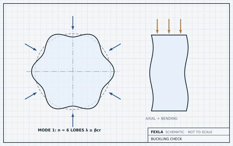
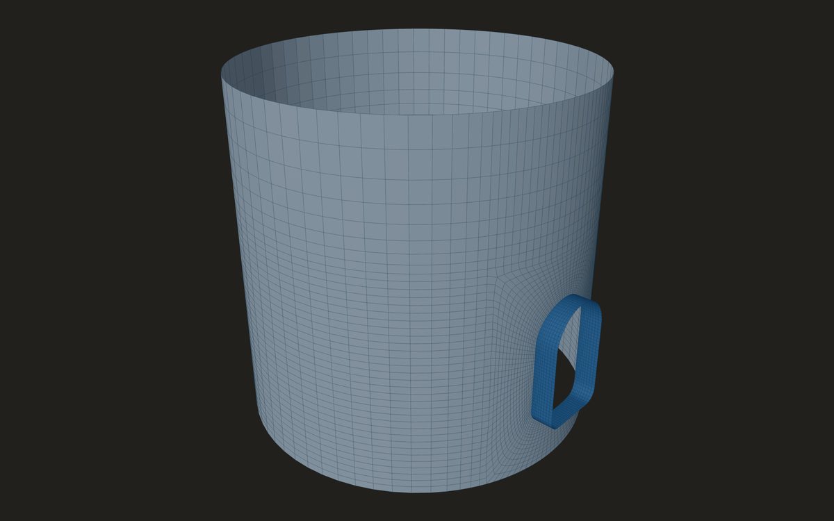
A skirt carries the vessel's weight and the wind or seismic overturning moment in axial compression, and with an access opening cut in it, it buckles earlier on the compression side. The check runs an eigenvalue buckling analysis for each VIII-2 Table 5.15 combination, with factors on the loads, then turns the load factor into a pass or fail by 5.4.2 Method A. Two sets of factors are in play, and keeping them apart is most of the work.
This post goes through them in order.
The basis of the wind and seismic loads
The foundation loads arrive from the site calculation: weight W, base shear V and base moment M, sometimes with a vertical seismic part. Wind and seismic codes often give strength-level values. The engineer says which basis they are on. Strength-level wind is taken at 0.6W and earthquake at 0.7E for the allowable-stress hand checks; values already at allowable-stress level are taken at 1.
The hand check of the skirt wall uses those factored loads: the required wall t_r = W/(π·Dm·Sc) + 4·|M|/(π·Dm²·Sc), at the base and at the opening's centre height, with Sc the allowable compressive stress, factor B, read by the engineer from the material chart.
The buckling combinations
- (1) P + D, and D alone when pressure is not acting.
- (2) 0.88·(P + D + L), and the same with P not acting.
- (4)/(5) 0.88·(P + D) ± k·(W or E), with k = 0.71 for wind or earthquake at strength level, and 0.71/0.6 = 1.18 for a row already at allowable level; reversed, and with P not acting.
The factors sit inside the combination. The load factor λ from each eigenvalue run is the margin on the combination as it stands, not on the unfactored loads. On a skirt the loads are written so that the opening side is in compression whatever its angle, and the reverse case is run as well.
From a load factor to a pass
A linear eigenvalue is the buckling load of a perfect shell. Real shells buckle lower, so Method A knocks it down by the capacity reduction factor βcr at the critical location, the element with the largest destabilising energy. For a cylinder in axial compression βcr = 338/(389 + Do/t), or 0.207 for a very thin shell; in hoop compression 0.80; on a formed head 0.124.
σm cancels from the uncapped test, so it comes down to βcr·λ ≥ 2. Once the cap applies it is σm ≤ 0.275·Sy. A large λ therefore does not guarantee a pass: on a stocky skirt the yield cap governs.
Negative load factors, the loads at which the shell would buckle if every load were reversed, are reported separately. A factor above a million is reported as no buckling. A run that does not converge is not assessed, never a pass. When the critical element lies next to a cut end of the model, the result says so.
What the opening does
On the example skirt the dev log records a load factor of 24.7 with the opening on the compression side and 43.1 with it on the tension side. A test asserts only the order, that compression is lower. That is the reason both directions are run: a skirt checked with the wind from the wrong side can look much safer than it is.
The buckling solver itself was checked on textbook cases: a thin cylinder in axial compression came out between 0.95 and 1.10 of the classical value E·t/(R·√(3(1 − ν²))), 1210 MPa for R = 250 mm and t = 2.5 mm, and a square plate within 2 % of its classical load. The skirt model spans the base ring to the head joint, both taken as lines of support, so the lobes form over the real length.
Where it stops
- 01Linear, perfect-shell buckling with Method A's knock-down; Method B, with imperfections and plasticity, is not available.
- 02A critical location in a plate that is not a shell of revolution, such as a stiffener bar, is reported as not covered by Method A.
- 03Sc for the hand check and Sy for the cap are typed by the engineer; FEXLA holds no Section II Part D charts.
- 04Buckling results are early access and under verification.
Try it in FEXLA
The Skirt access opening card runs the skirt's buckling analysis for every Table 5.15 combination, with the opening on the compression and tension sides.
Open the cardReferences
- ASME Section VIII Division 2, 5.4.1 and 5.4.2 (Method A), Table 5.15 (combinations), Table 5.3 (factors on wind and earthquake).
Method notes this draws on
Next post: Vacuum vessels with attachments: what changes
Educational article. It explains principles and is not design guidance; follow your governing code and edition.