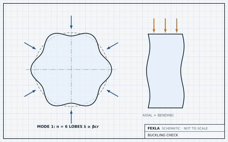
Under vacuum or external pressure a shell can fail by buckling before any stress limit is reached, so an attachment check on a vacuum vessel needs a buckling check beside the stress check. The model must then span the shell between its lines of support, not a short band round the attachment, and the pressure must follow the wall as it deflects. Attachment loads that push in, or add compression to the shell beside the attachment, can lower the buckling load further.
This post covers what changes from an internal-pressure check, and what the tool does today.
Pressure from outside
In the shell model a negative design pressure is external pressure. The arrows in the loads figure turn round, and the thrust on a closed nozzle now pushes the nozzle into the shell. A sign slip here is the most likely input mistake on a vacuum vessel, so check the loads figure before reading any result.
One design pressure is run per model, and its sign decides internal or external. Most vacuum vessels also see internal pressure. The two conditions never act together, so they are run as two cases.
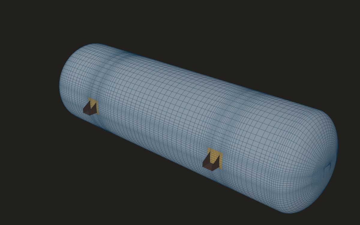
The model spans the lines of support
For stress, a band of shell a few decay lengths round the attachment is enough. For buckling under external pressure it is not: the shell buckles in lobes over its whole unsupported length, and the cut ends of a short band would hold it round where the real shell is free. So the span between lines of support is entered, with the attachment's place in it. The model then covers the span, its ends held round and free to rotate, one end held along the axis.
With no span given, the model is a long cylinder whose ends are free to go oval. That buckles at a lower load than the real shell, which is conservative, and the result says so.
A span longer than eight outside diameters is also treated as a long cylinder. That is earlier than the code's own long-cylinder limit, so between those lengths the model's load factor is lower than the shell's, while the rule shown beside it uses the real span. It errs on the safe side, and the note says so.
Pressure that follows the wall
External pressure stays normal to the wall as the wall deflects. That adds a load stiffness to the eigenvalue problem. Without it a long cylinder's buckling pressure comes out too high by n²/(n² − 1), with n the number of lobes. The buckling solver includes it, and it was checked on a long cylinder free to go oval: within 2 % of 3D/R³, which is 0.733 MPa for R = 506 mm and t = 12 mm.
How an attachment lowers the buckling load
- A radial push or a moment adds local compression beside the attachment, where the opening has already taken out stiffness.
- A large opening lowers the shell's own lobed mode over the span.
- Clip and lug loads on a thin vacuum shell make local patches of compression.
Each Table 5.15 combination puts the attachment loads together with the pressure, at the combination's factors, and each is run with the pressure acting and not acting. The load factor and Method A then give the verdict. For a cylinder, the plain-shell rule of VIII-2 4.4.5.1 over the same span is shown beside it as a cross-check; above Do/t of 2000 that rule is not assessed.
VIII-2 4.5.17.1 limits the opening rules for external pressure to openings no larger than a quarter of the cylinder's diameter and 80 % of the ring spacing. Larger openings go to Part 5, which is this analysis.
Where the critical location is
Method A's knock-down factor depends on where the shell buckles: a cylinder or cone, a formed head, or a nozzle neck, which is taken with the cylinder rules at the nozzle's own D/t. If the critical location is in a clip, lug, leg, ring or gusset plate, Method A does not cover it, and the tool says so rather than passing it.
On a stocky shell the capped critical stress, 0.55 times yield, sets the limit before the load factor does. That cap is where Method A stops being a good guide, and the result notes that Method B is not available. Thin vacuum shells, where the buckling is elastic and the critical location is the cylinder or the head, are where Method A fits best.
Where it stops
- 01Stiffening rings are not offered on this card yet; a ring is taken as a line of support at the end of the span.
- 02Internal and external pressure are separate runs.
- 03Head and cone rules for external pressure are not shown; only the cylinder rule is.
- 04Method B, with imperfections and plasticity, is not available, and buckling is not run on solid models.
- 05Buckling results are early access and under verification.
Try it in FEXLA
The Buckling check card runs eigenvalue buckling with the attachment loads and external pressure over the span, by VIII-2 5.4.2 Method A.
Open the cardReferences
- ASME Section VIII Division 2, 4.4.5.1 (cylinders under external pressure), 4.5.17.1 (opening limits), 5.4.2 (Method A), Table 5.15.
Method notes this draws on
Next post: Limit load against the elastic check: rescuing a failing nozzle
Educational article. It explains principles and is not design guidance; follow your governing code and edition.