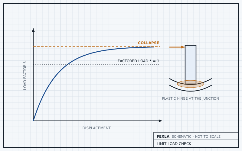
When a nozzle fails the elastic primary checks by a small margin, VIII-2 5.2.3 offers another route: a limit-load analysis with an elastic-perfectly plastic material at 1.5S and factored loads. If the model still finds equilibrium at the full factored load, the primary rows it covers are met, and no stress classification is needed. The secondary, fatigue and buckling checks stay as they were.
This post covers when the route helps, what a pass replaces, and the cautions on a local model.
Why the elastic check can fail a sound nozzle
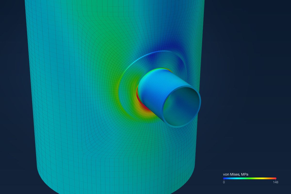
At a nozzle junction the elastic stress mixes membrane, bending and secondary parts, and classifying them is a judgement. Local primary membrane PL and local membrane plus bending PL + Pb are compared with limits that assume the stress cannot redistribute. A real junction yields locally and passes load round the yielded zone. The elastic check does not credit that, so it can fail a nozzle that would carry the load.
What the analysis solves
Each shell layer point yields at 1.5S by von Mises and does not harden. Displacements are small. The factored load rises from zero in steps, and the step ends either at the full load, a pass, or where the structure stops finding equilibrium, a fail. A run stopped by time or by a solver error is not assessed, never a pass.
Each combination of VIII-2 Table 5.4 is its own load path from zero, since plastic results do not superpose. Pressure not acting, live load not acting and reversed occasional loads are run too. A combination that is a smaller multiple of one that already converged is covered without a run of its own. Thermal and other displacement-controlled loads are left out: they do not change an elastic-perfectly plastic limit load.
What a pass replaces
- It replaces the elastic primary rows, Pm, PL and PL + Pb, in the run where both were done.
- It does not replace the primary plus secondary range, ratcheting or fatigue: those still come from the elastic analysis.
- It does not replace buckling. Under external pressure the tool notes that limit load does not cover buckling.
- It says nothing about strains or about loss of stiffness from shape change.
So the route rescues a nozzle that fails on primary stress. A nozzle that fails on the secondary range, or on fatigue, needs a different change: geometry, a pad, or a better load case.
Cautions on a local model
- Local collapse is what the model finds: hinge lines and yielded patches round the nozzle. Collapse of the vessel as a whole, overall bending or a support system, is outside a model of the nozzle.
- If the plastic zone reaches a cut end of the model, the held end can carry a hinge the real shell would not, and the answer can be unconservative. Keep the cut ends well clear of the nozzle and check where yielding has spread.
- Thick walls, Rm/t at or below 4.5, and parts loaded mainly in bending raise a warning.
- The route is VIII-2 only: S must be the Division 2 value. Models above 15 000 elements are refused.
After a pass the run continues toward three times the factored load to find the collapse factor. It is reported as a margin only when the stop is a true limit bracketed within 0.2 %. It is a small-displacement limit load, not a burst pressure.
Against CalculiX, a nozzle on a cylinder came within −2.0 % of the reference limit load, and a closed cylinder within 0.12 % of its closed form.
Run time grows with the model. Above 1500 elements the solver switches to a quasi-Newton method and confirms any failure by full Newton before it counts. In the validation record a 4178-element model took 13 to 14 s and a 12 194-element model about 48 s in Node. Models above 5000 elements raise a warning.
Where it stops
- 01Small displacement and perfect plasticity: no strain limits, no hardening, no large-displacement collapse.
- 02Local collapse of the modelled part only, not of the vessel.
- 03The secondary range, ratcheting, fatigue and buckling are not replaced.
- 04Limit-load results are early access and under verification.
Try it in FEXLA
The Buckling check card runs the VIII-2 5.2.3 limit-load analysis on the same shell model, combination by combination, with a collapse margin where it can be bracketed.
Open the cardReferences
- ASME Section VIII Division 2, 5.2.1.4 and 5.2.3 (limit-load analysis), Table 5.4 (load factors).
Method notes this draws on
Next post: Agitator nozzle fatigue from rotating bending
Educational article. It explains principles and is not design guidance; follow your governing code and edition.