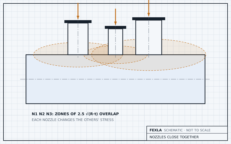
Two attachments interact when the zones of local stress round them overlap. Each zone reaches a few decay lengths √(R·T) from the attachment edge; at 2.5 of them the local bending is down to about 4 % of its value at the edge. Closer than that, a WRC 537 check of each attachment on its own misses the stress the neighbour adds.
This post sets out how to judge the spacing, why single checks fall short, and how the shell model checks a group.
How close is close
Local bending in a shell oscillates and dies out away from the load, with an envelope that falls as e^(−βx), where β = 1.285/√(Rm·T) for steel and x is the distance from the attachment edge. The natural unit of distance is √(Rm·T).
For clips, Moss gives a shorter rule of thumb, coded in the calculator's shape helpers: clips nearer than √(R·t) round the shell, or 6 in (152.4 mm) along it, act as one attachment.

Why single checks miss it
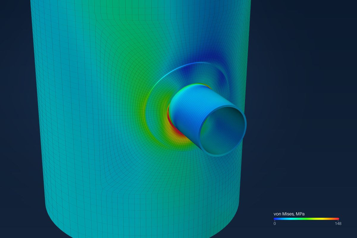
WRC 537 takes each attachment as rigid and alone on an otherwise plain shell. It has no input for a neighbour, so it cannot see one. Two things go wrong when there is one. The neighbour's local stress adds to this attachment's at the points between them. And the governing point moves: WRC 537 reports four points round the edge because shell theory puts the peak there for an isolated attachment, which stops being reliable once another attachment is near.
Adding the two WRC 537 results by hand is no fix: each one is valid only at its own edge, and neither knows the shell between them is stiffened by the other.
Pads make the gap shorter than it looks. A pad edge is a second edge, where the shell is back to its own thickness and the pad acts as the attachment, so the zone starts there. Two padded nozzles whose centres look well apart can have pad edges inside each other's zone.
The same applies to the ends of the shell. WRC 537, 4.5.2 assumes an attachment loaded by a moment sits at least half the mean radius from the end of the cylinder, and the calculator calls for a shell model when it does not. A head joint or a cone junction is a neighbour in its own right.
The shell model of a group
The shell model takes up to four attachments on one shell or head: nozzles, clips or a mix, each with its own size, pad and load rows. They are meshed on one parent with shared nodes, so the stress between them comes out of the model rather than from an assumption.
- Each attachment gets its own refined zone, as for one. Where the zones of neighbours would overlap they shrink together, to a fifth of their size at most.
- Attachments closer than that are refused with the clearance needed. Footprints that overlap are refused.
- Results are reported per attachment: the worst check at each, and which attachment governs.
- A fifth attachment is refused; model the others in a separate run.
The same spacing rule appears in the lifting job: two tailing lugs side by side must leave room on the arc for the pad footprint plus six element rows, or the half-angle between them is refused.
In practice
- Measure the clear distance between edges, including pads and welds, not between centrelines.
- Compare it with 2.5·√(Rm·T) on the corroded shell. Closer than that, a group model is the safe check.
- Run each attachment by WRC 537 as well. Where the group model and the single checks agree, the interaction is small; where they differ, find out why before trusting either.
- Remember heads, cone junctions and seams count as neighbours too: they disturb the shell the same way.
Where it stops
- 01Up to four attachments on one parent; overlapping footprints are refused.
- 02The model is linear and bonded; parts that only touch are not modelled.
- 03The shell model is early access and under verification.
- 04WRC 537 itself has no neighbour input; the spacing check is the engineer's.
Try it in FEXLA
The Nozzles close together card models two to four attachments on one shell or head, each with its own loads, and reports which one governs.
Open the cardReferences
- WRC Bulletin 537.
- D. R. Moss and M. Basic, Pressure Vessel Design Manual, 4th ed., Procedure 7-3 note 2.
Method notes this draws on
Next post: Clips and platform supports: entering a footprint
Educational article. It explains principles and is not design guidance; follow your governing code and edition.