WRC 537 checks a clip as a rigid rectangle on a cylinder, given by its half-width round the shell, C1, and its half-length along it, C2. A plain plate clip is entered by its own size. A tee, I, channel, box or angle is entered as the equivalent rectangle from Moss, Procedure 7-3, which the calculator works out from the section's width and length.
This post covers what goes into those two numbers, and what the clip check does not see.
The rectangle the curves need
The coefficients for a rectangular attachment are read against γ = Rm/T and a pair of ratios formed from C1 and C2. The curves cover C1/C2 from 1/4 to 4. A clip outside that range is read at the limit, and the result says so and suggests a shell model.
The fillet weld round the clip is part of the footprint: the clip half-lengths include the weld leg. With a pad, the pad edge is a second rectangle, the pad's own size plus its weld, checked on the shell thickness alone.
On a clip with a pad, the allowable at the clip edge is the lower of the shell's and the pad's. At the pad edge only shell metal is present, so only the shell's allowable applies there, and the shear is spread over the pad's sides on the shell thickness alone. Either edge can govern, and the report shows both.

Rolled and built-up sections
A structural section does not load the shell evenly over its outline: the webs and flanges carry more than the space between them. Moss, Procedure 7-3, Fig. 7-10 gives factors that turn a section of width b (round the shell) and length h (along it) into an equivalent rectangle, C1 = c1·b and C2 = c2·h.
| Section | c1 | c2 |
|---|---|---|
| Single plate | 0.5 | 0.4 |
| Two plates close together | 0.3 | 0.4 |
| Plate on a base plate (tee) | 0.25 | 0.4 |
| Two plates on a base plate | 0.3 | 0.4 |
| I section | 0.4 | 0.5 |
| Box section | 0.5 | 0.5 |
| Channel | 0.3 | 0.5 |
| Angle | 0.2 | 0.4 |
Moss gives these factors for the placement he draws: b round the shell, h along it. A member turned the other way has no rule, so the calculator offers none. Use the shell model, or enter the two lengths yourself on your own basis.
Loads on a clip
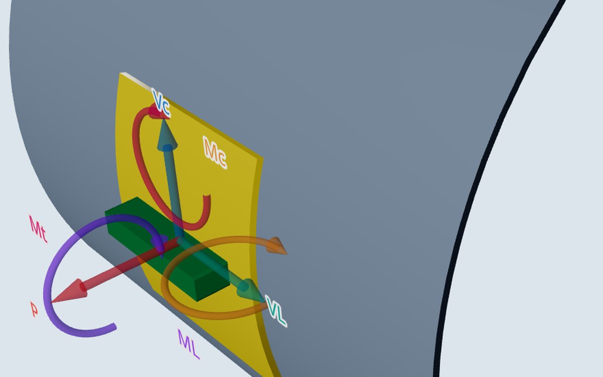
The six loads act at the clip centre on the shell surface. The radial load and the two moments give membrane and bending at the eight points round the clip edge. The shears give shear stress spread over the clip's sides, VC/(4·T·C1) and VL/(4·T·C2).
Torsion is collected and printed, but it adds no stress on a rectangular attachment: the bulletin states that no accepted method is available for it. A clip with a large torsion needs the shell model.
When to go to the shell model
- Clips on heads and cones: WRC 537 takes clips on the cylinder only.
- Offset clips, members turned against Moss's placement, and large torsion.
- An equivalent-size clip whose stress ratio reaches 0.7. The size is a rule of thumb, so the calculator suggests the model well short of 1.0.
- Clips close together. Moss's rule of thumb treats clips nearer than √(R·t) round the shell, or 6 in (152.4 mm) along it, as one attachment.
The shell model builds the actual section from its plates, standing on the shell with shared nodes, so the load spreads into the shell the way the section carries it.
Where it stops
- 01The shell at the clip edge is checked. The clip itself, its welds and the platform steel are not.
- 02The equivalent rectangle is an approximation from Moss, not a derivation.
- 03WRC 537 takes clips on a cylinder only; heads and cones go to the shell model, which is early access and under verification.
Try it in FEXLA
The Clips, brackets and platform supports card checks plate, tee, I, channel, box and angle clips by their footprint, with the shell model for heads, cones and offset clips.
Open the cardReferences
- D. R. Moss and M. Basic, Pressure Vessel Design Manual, 4th ed., Procedure 7-3 (Fig. 7-9, Fig. 7-10, notes 1 and 2) and Procedure 7-4 note 3.
- WRC Bulletin 537.
Method notes this draws on
Next post: Agitator nozzles: loads, gussets and fatigue
Educational article. It explains principles and is not design guidance; follow your governing code and edition.