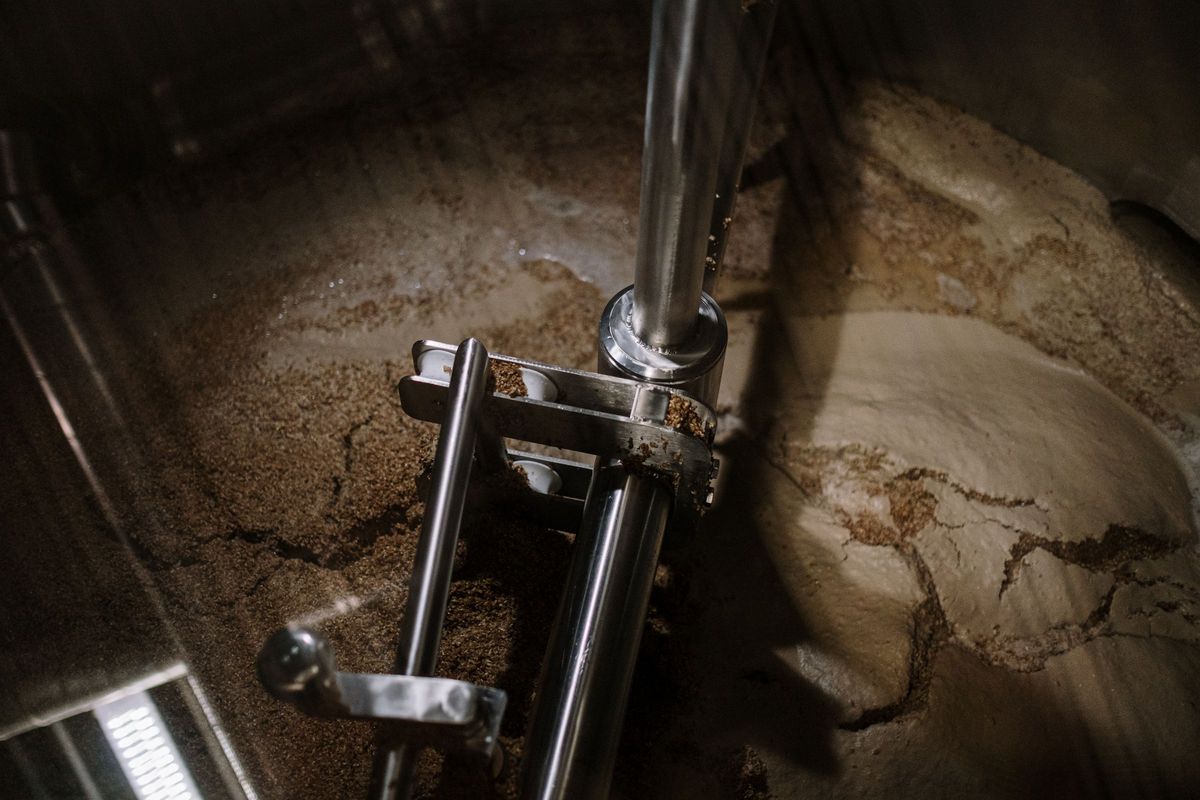
An agitator nozzle carries the weight, thrust and torque of the drive as steady loads, and a shaft bending moment that turns with the shaft. At a fixed point of the nozzle that moment reverses once every revolution, so over a design life it reaches hundreds of millions of cycles. The fatigue check at the welds, not the static stress, is usually what decides the nozzle.
This post goes through how the agitator job turns the vendor's data into load rows, cycles, gussets and a flange tilt check.
Which load goes in which row
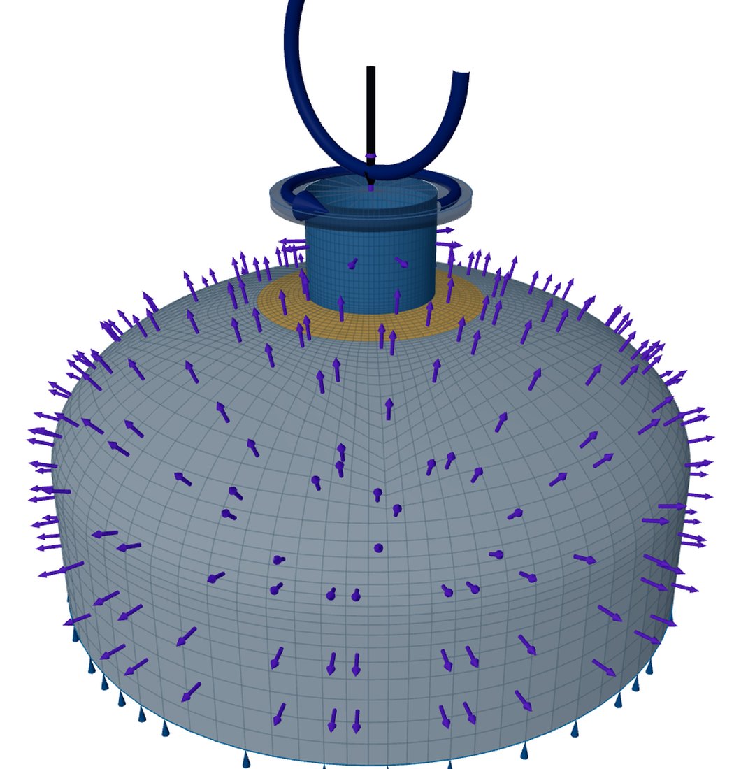
The job builds an ordinary shell model: a nozzle at the centre of a top head, the mounting flange face as the loaded end. It only fills in the same inputs the workbench shows, and they stay editable. The loads are the vendor's, given at the flange face.
- Weight, axial thrust and torque act while the machine runs. They go in the weight row, a sustained primary load: axial force = thrust − weight, and the torque about the nozzle axis.
- The shaft bending moment turns with the shaft. It goes in the operating row as a load-controlled load with reversal on.
- The loads act at the flange face, so the lever of any shear is not added: only what the vendor gives at the face acts, and the head sees it through the neck.
Torque from power, cycles from speed
The code counts one bending cycle per revolution and gives it to the fatigue analysis as an event that swings the operating row from −1 to +1 at operating pressure, so the range is twice the vendor's moment. Start-ups are counted separately, from shutdown to operating.
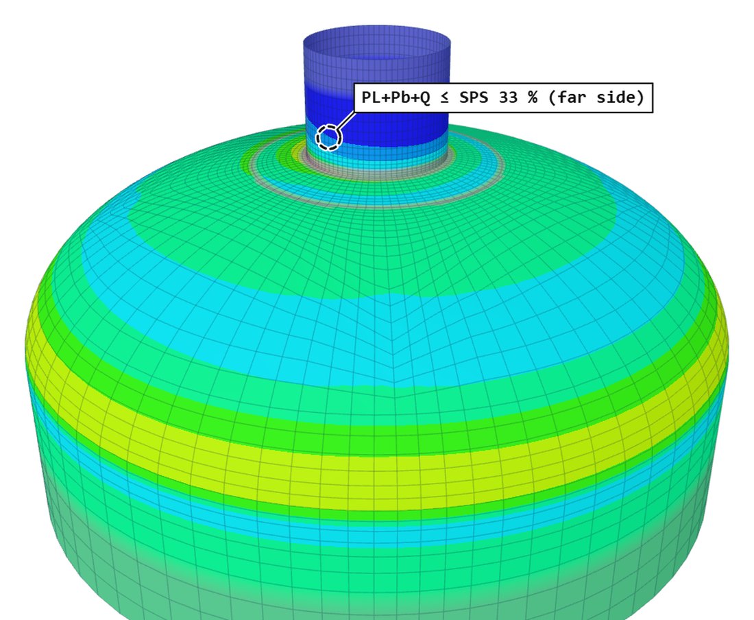
On that default the dev log records a nozzle that passes the stress checks at 34 % while the welded-joint fatigue check fails. The stress ratio does not tell it: a reversing moment at 90 rpm is a very high cycle count.
Gussets round the nozzle
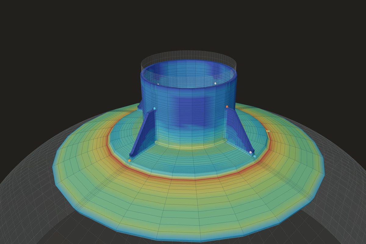
Gussets between the neck and the head are entered as 2, 4 or 8 radial plates at multiples of 45°, with height, width, thickness and weld leg. On a round neck without a heavy barrel they are meshed with the nozzle, and the gusset toe on the head becomes a weld line of the fatigue check. On a heavy barrel they stay out of the mesh, and the flange tilt is then an upper bound.
Each gusset is also hand-checked as a bracket. All of the bending moment at the head is given to the gussets, an upper bound on their force. Four or eight share it evenly in any direction. Two carry only the moment in their own plane; the agitator's rotating moment passes through the direction they do not cover every revolution, where the bare neck carries it. The plate is checked as Moss's assumed column (Procedure 4-13), the base on the head and the neck edge in shear, and the fillet welds against Moss 10-3.
Flange tilt
For each load case a rigid motion is fitted by least squares to the displacements of the flange-face ring. The rotation across the nozzle axis is the face tilt; times the flange radius it is the face deflection.
The dialog shows typical limits of 0.05° tilt and 0.5 mm at the outside diameter, marked to be confirmed with the vendor. On a 597 mm flange, 0.05° is 0.26 mm at the outside diameter, so the tilt limit governs there.
Where it stops
- 01The agitator's loads come from its vendor. Shaft dynamics, blade-pass and other harmonics, hydraulic unbalance and resonance are not computed; the vendor's bending moment must include them.
- 02One stress cycle per revolution only.
- 03The end is a rigid plane; the gearbox and shaft stiffness are not modelled, and the flange is drawn, not meshed.
- 04The agitator job is early access and under verification, and is not a substitute for the vendor's and the engineer's review.
Try it in FEXLA
The Agitator nozzle card builds the top-head model from the vendor's loads, with fatigue from speed, hours and starts, the gussets and the flange tilt.
Open the cardReferences
- ASME Section VIII Division 2, Part 5: 5.5.3 and 5.5.4 (fatigue, welded joints), Table 5.6.
- D. R. Moss and M. Basic, Pressure Vessel Design Manual, 4th ed.: Procedure 4-13 (gussets), 10-3 (welds).
Method notes this draws on
Next post: Lifting lug checks by Moss and AISC
Educational article. It explains principles and is not design guidance; follow your governing code and edition.