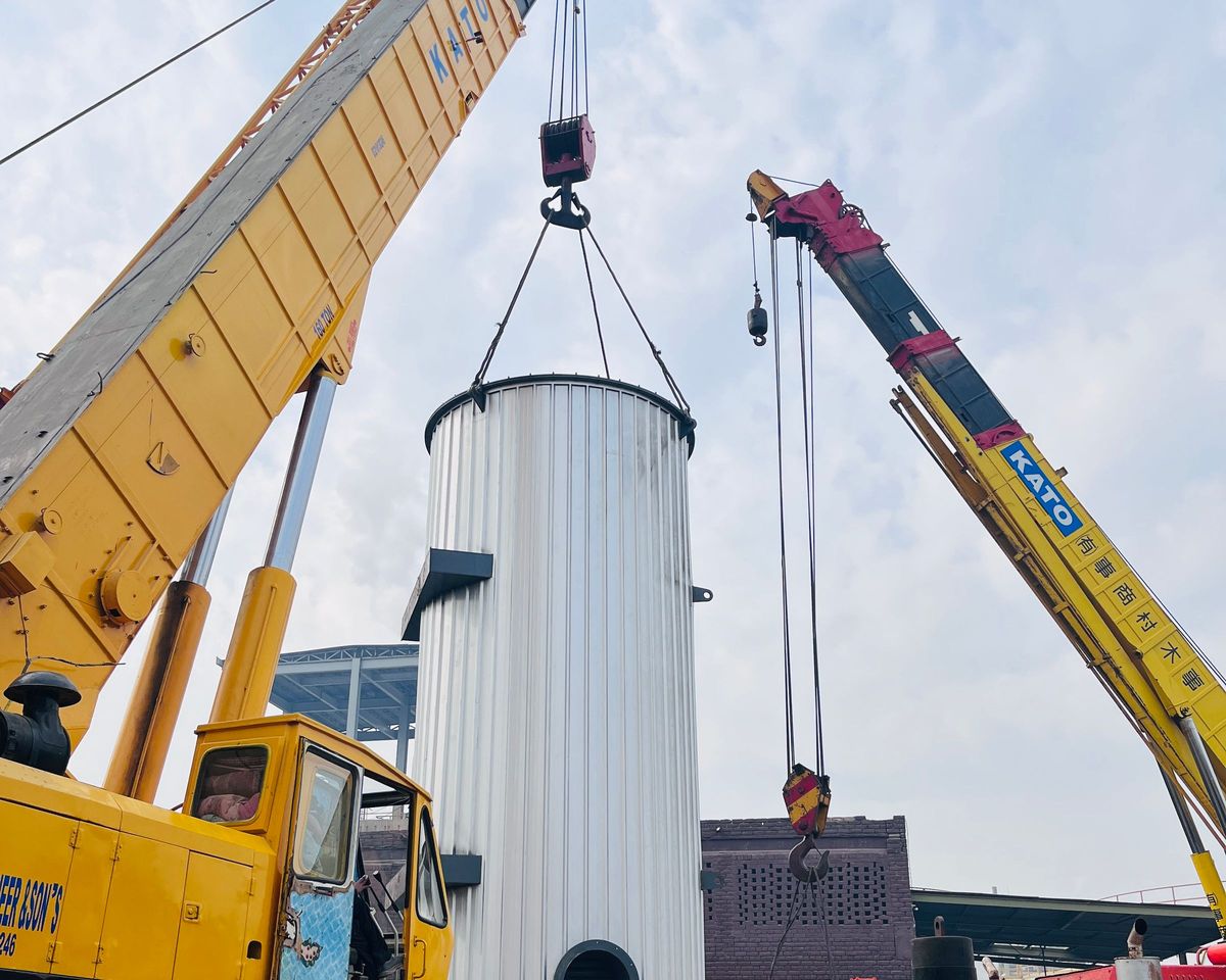
A lifting lug is checked in three parts: the lift as statics, to find the load on each lug at each angle; the lug plate by Moss and AISC allowable stresses on the factored load; and the shell under the lug, by WRC 537 or a shell model. The shackle is the maker's rating, checked for fit.
This post works through those parts for an upending lift: top lugs on the pick crane, a tail lug on the tail crane.
The lift as statics
The vessel is taken as rigid with both hook lines vertical. It is turned about the tail pin from horizontal to vertical in the angle steps listed; the default is every 15°. At each angle the moments about the tail pin give the pick load, and the tail takes the rest.
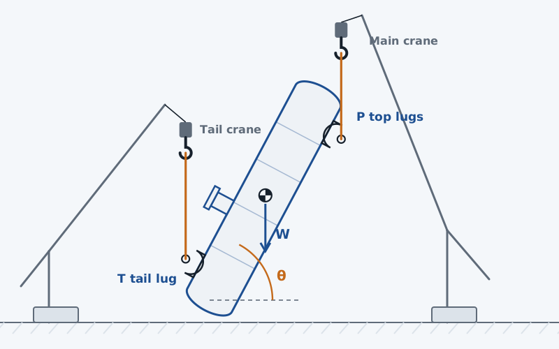
Two cases are flagged rather than hidden. If the centre of gravity passes beyond the pick point, the tail goes slack and the vessel hangs from the pick lugs. If it falls behind the tail pin, the pick load goes negative and the arrangement cannot hold the vessel.
Two weights: one for the shackle, one for the steel
The statics are run twice. Once on the erection weight W_E, unfactored, for the shackle: the maker's design factor already carries impact. Once on W_L = K_L·W_E for the lug, the welds and the shell. Moss gives K_L, the overall factor for impact and safety, as 1.5 to 2.0. Below 1.5 the tool warns; below 1.8 it warns that the checks do not reach the F_y/3 basis of ASME B30.20.
The lug plate
The lug load is resolved into the plate's axes: along its base, normal to it (the pull), and across the plate (the side load, at least 10 % of the lug load by Moss). The hole checks take the full resultant. The base checks take the components separately.
- Net section at the pin hole: P / ((A − D1)·t) ≤ 0.45·F_y, with cheek plates adding to t.
- Shear above the hole: P / ((R − D1/2)·t) ≤ 0.4·F_y.
- Bearing on the pin: P / (D2·t) ≤ 0.9·F_y.
- Base: axial and the two bendings in an interaction ≤ 1, in-plane bending at 0.6·F_y and across-plate bending at 0.75·F_y; base shear ≤ 0.4·F_y.
- Base fillet welds: leg = line force / (0.707·F_s), F_s 108.9 MPa for E70XX and 93.8 MPa for E60XX (Moss 10-3).
Shackle fit and trunnions
The tool does not rate a shackle: ASME B30.26 leaves the rating and design factor with the maker. It checks four fits: the pin passes the hole, the plate with its cheek plates fits the jaw, the bow clears the lug top, and the lug load on W_E is within the working load limit.
A trunnion is a round tube welded to the shell, with the sling a distance e out. It is checked as a beam (Moss 10-8 Type 3) on W_L: bending M = V·e against 0.66·F_y, shear 2V/A against 0.4·F_y, an interaction with the sling pull, and the root weld as a ring, with a minimum throat of 9.5 mm.
The tail end
Two tailing lugs at ±β about the lift plane each take half the tail load, resolved into their own planes. The tool checks that the two stay far enough apart for the mesh. A tail beam under the skirt is checked by Moss 10-5 in bending, bolts and skirt crippling. The skirt base ring under a tail lug is checked as Moss's one-point ring with Table 10-7's coefficients in closed form, evaluated every 0.5° and enveloped.
The shell under the lug
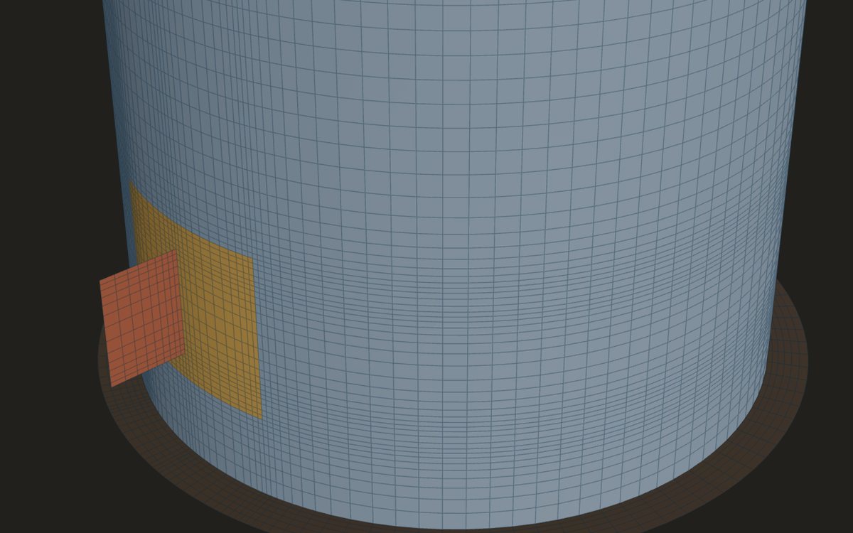
The hand checks know nothing of the shell's local stress at the lug. The lifting card checks the shell under each lug by WRC 537, and builds a shell model of the lug, its pad and a band of shell where the result comes close. The model applies the lug load at the pin line and leaves out the pin hole, the shackle and the base ring, which are the hand checks' job. Report the two side by side: they answer different questions.
Where it stops
- 01The vessel is rigid and the lift quasi-static: no dynamic amplification beyond K_L, no wind, no crane or boom geometry. Crane selection and the lift plan are not checked.
- 02The governing step is the largest lug load among the listed angles, not an interpolated maximum.
- 03There is no sleeve, pin or retaining-plate check for the sling end of a trunnion.
- 04Plain plate lugs and trunnions only.
- 05The shell model of the lug is early access and under verification.
Try it in FEXLA
The Lifting and tailing lugs card runs the lift statics, the lug, weld and shackle checks, and the shell under each lug.
Open the cardReferences
- D. R. Moss and M. Basic, Pressure Vessel Design Manual, 4th ed.: 10-3 (welds), 10-4 (lift loads), 10-5 (tail beam, base ring, Table 10-7), 10-8 (trunnion).
- AISC allowable stress design, as used in Moss.
- ASME B30.20 (below-the-hook lifting devices), ASME B30.26 (rigging hardware).
Method notes this draws on
Next post: Vessel on legs: Moss Chapter 4 checks
Educational article. It explains principles and is not design guidance; follow your governing code and edition.