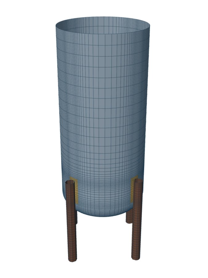
A vertical vessel on legs is checked in two halves. The legs, base plates and anchor bolts follow Moss, Pressure Vessel Design Manual, Chapter 4, with AISC allowable stresses. The shell where each leg is welded is a local stress problem, checked by WRC 537 for a leg on the cylinder and by a shell model otherwise.
This post goes through the hand checks in the order they are made, then the shell.
Loads at the base
Wind and seismic arrive as a base shear V and an overturning moment. They are entered as resultants from the site calculation, or worked here from a simple pressure on the projected area or a horizontal g-factor. The engineer says whether they are at strength level, taken as 0.6W and 0.7E, or already at allowable-stress level. No one-third increase is taken for occasional loads, as ASME Section VIII Division 2 Table 5.3 does not take one.
Each case (empty, operating, test, with wind or seismic) is run for each load direction. The overturning moment is resolved into leg loads at the top of the leg attachment.
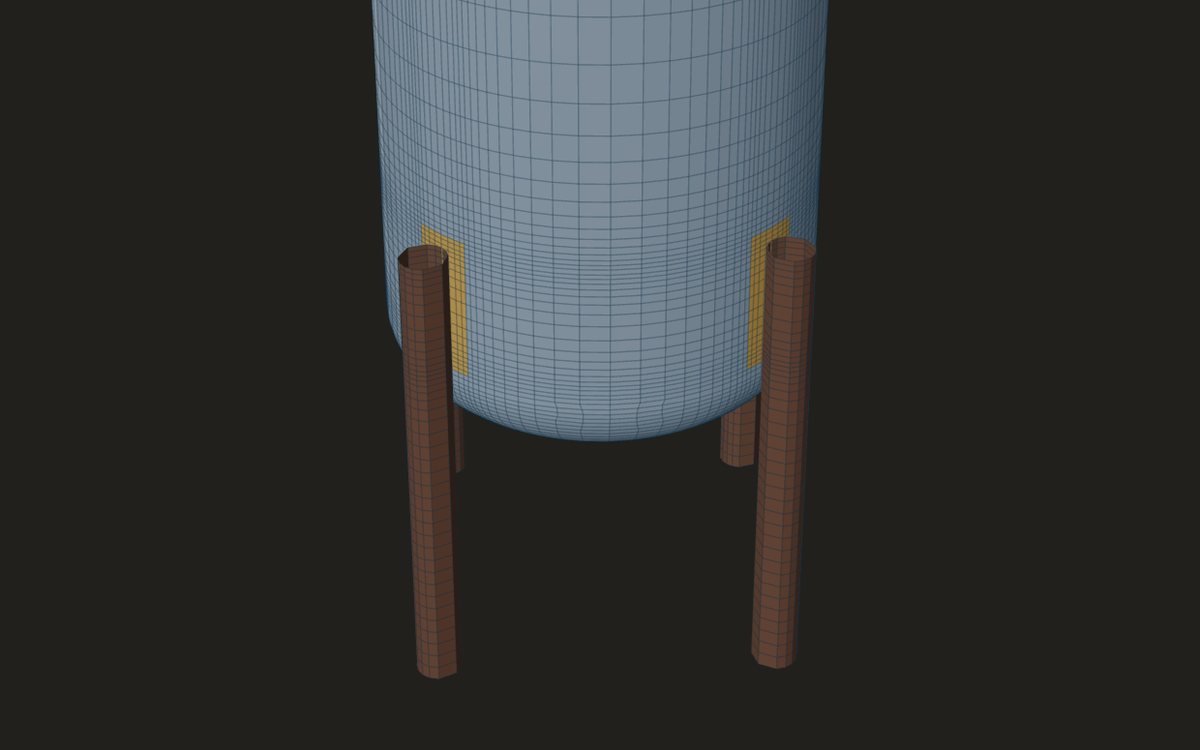
The load on each leg
The tool goes further than the one formula. The vertical share of each leg follows Moss Table 4-11, exact for any leg count and either load direction. The horizontal shear goes to each leg by its stiffness across the load. Legs are taken as pinned at the base and fixed at the vessel, so a leg bends under its eccentric load and under its share of the shear times its free length.
The leg as a column
Each leg carries axial load and bending together. The allowable axial stress Fa comes from AISC E2 for the leg's slenderness KL/r; Fb is 0.66·F_y for a compact section and 0.60·F_y otherwise. The interaction is AISC H1, with Cm = 0.85 and the Euler term where fa/Fa is above 0.15.
- K is 1.5 to 2.0 for unbraced legs, as Moss gives, and 1.0 for braced legs. A KL/r above 200 is flagged: brace the legs or use a stiffer section.
- A leg in uplift is checked in tension at 0.6·F_y.
- The lateral deflection y = V·ℓ³/(3·E·ΣI) is held to ℓ/200, Moss's 6 in per 100 ft, and gives the period of the vessel on its legs.
Braced legs
With cross bracing (Moss 4-5) the shear goes through the braces, shared between the panels by their direction, and the legs carry no shear-times-length bending. Each brace is checked in tension at 0.6·F_y; Moss allows a 1.2 increase for wind or seismic, and it is not taken. With two rods per panel, the compression rod is checked as a column over half its length if the rods are pinned where they cross, or the whole length if not.
Base plates and anchor bolts
The base is pinned, so the base plate sees the axial load only (Moss 4-12): bearing P/(B·D) against the concrete allowable, and the plate thickness from its cantilever beyond the section. Anchor bolts (Moss 4-16) are needed when the weight is less than 4M/d. Their area follows from (4M/d − W)/Sb, and their shear from V over the bolt area when there is no uplift.
The shell at each leg
Above each leg the shell is in compression. The tool checks fc = f1/(L1·t), with L1 the leg attachment width plus 2√(R·t), against the external-pressure factor B, and the weld shear f1/(2h). Then the local stress: for a leg on the cylindrical shell, the governing leg's loads are passed to a WRC 537 clip check at the junction. Legs coped at a cone junction, legs wholly on a head, and top platform legs go to the shell model.
Where it stops
- 01Wind and seismic loads are yours to give; they are not derived from a site code here.
- 02The leg's F_y and E at design temperature are typed by the engineer; FEXLA holds no Section II Part D tables.
- 03The base is pinned. A fixed base, a base plate under moment and a concrete foundation check are not in the method.
- 04The shell model for legs on heads and cones is early access and under verification.
Try it in FEXLA
The Vessel on legs card runs the Moss Chapter 4 hand checks, hands the shell at each leg to WRC 537, and builds the shell model for legs on a head or a cone.
Open the cardReferences
- D. R. Moss and M. Basic, Pressure Vessel Design Manual, 4th ed., Chapter 4: 4-1, 4-3, 4-4 (unbraced legs), 4-5 (braced legs), 4-12 (base plates), 4-16 (anchor bolts).
- AISC allowable stress design: E2 (columns), H1 (combined stress), D1 (tension).
- ASME Section VIII Division 2, Table 5.3 (factors on wind and earthquake).
- WRC Bulletin 537, for the shell at a leg on the cylinder.
Method notes this draws on
Next post: Skirt access openings and buckling
Educational article. It explains principles and is not design guidance; follow your governing code and edition.