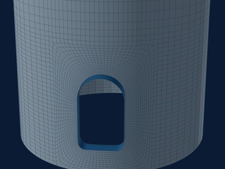
A skirt carries the vessel's weight and the wind or seismic overturning moment as axial compression, and an access opening cuts a piece out of that load path. The wall beside the hole takes the load the hole removed, its corners concentrate it, and on the compression side the weakened wall buckles earlier.
The skirt card checks this three ways: the skirt wall thickness for axial compression, the opening's reinforcement under axial compression by ASME Section VIII Division 2, 4.5.17.3, and a shell model with an eigenvalue buckling analysis.
Loads at the base
The inputs are a foundation load summary: weight W, base shear V, base moment M, and optionally a vertical seismic part and an eccentric-weight moment. The tool turns them so that the opening side is in compression whatever the opening's angle, and checks wind or seismic from the other side too. Above the opening the stress follows beam theory:
A test confirms that the shell model reproduces this stress above the opening within 5 %.
Hand check 1: the skirt wall
Sc is entered by the engineer, as factor B from the external-pressure chart in Section II Part D; the tool reports A = 0.125/(Ro/t) to read it. The check runs at the base and at the opening's centre height. The loads carry the factor of their basis: 0.6 for wind, 0.7 for earthquake, 1 when already at allowable level.
Hand check 2: the opening under axial compression
Division 2, 4.5.17.3 asks for an area of reinforcement Ar that depends on the opening size against √(R·t):
The area available is the shell beyond what it needs within 0.75√(R·t) each side, the sleeve outside and inside, the fillet welds and any pad. The check passes when it is at least Ar. Openings wider than 25 % of the diameter, the limit of 4.5.17.1, are flagged.
The shell model
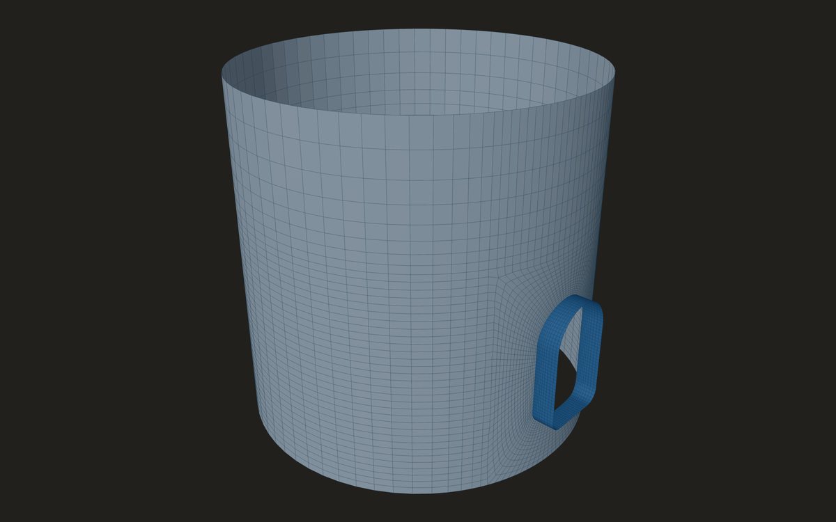
The model spans the whole skirt, from the bottom of the base ring to the skirt-to-head joint, both held as lines of support. The opening is tombstone, obround or round, with its sleeve, inside and outside projections, an optional pad and vertical stiffener bars either side. The mesh follows the decay length √(R·t), refined in rings to the exact sleeve-to-shell intersection. Pressure, temperature and cycles are off.
Buckling: from a load factor to a pass
Compression adds a negative term to the shell's stiffness. The eigenvalue analysis finds the factor λ on the load at which the total stiffness goes singular, for each combination of Table 5.15. A linear, perfect shell overstates the real buckling load, so Division 2, 5.4.2 Method A reduces it by a capacity reduction factor βcr at the critical element: for a cylinder in axial compression βcr = 338/(389 + Do/t), or 0.207 when Do/t is 1247 or more.
Read another way, the check needs βcr·λ ≥ 2. For the skirt above, Do/t = 189.5 gives βcr = 0.584, so the smallest load factor that passes is about 3.4. An opening on the compression side buckles at a lower factor than the same opening in tension; a test checks that ordering.
Where it stops
- 01The base ring, anchor bolt chairs, gussets and the skirt-to-head weld are not modelled; the ring and the head joint are lines of support.
- 02Sc is entered; the external-pressure charts are not in the tool.
- 03Buckling is linear and perfect, with all the knock-down in βcr. Method B (5.4.3, elastic-plastic with imperfections) is not available.
- 044.5.17.1 also limits the opening against the ring spacing; only the 25 % diameter limit is checked.
- 05The skirt opening job is early access and under verification against hand checks and an independent solver.
Try it in FEXLA
The Skirt access opening card builds the skirt with its opening, runs the two hand checks beside the model, and checks buckling under weight and wind or seismic.
Open the cardReferences
- ASME Section VIII Division 2: 4.5.17.1 and 4.5.17.3 (openings under axial compression, eqs. 4.5.222 to 4.5.225), 5.4.2 Method A (eqs. 5.13 to 5.17), Table 5.15.
- ASME Section VIII Division 1, UG-23(b) (factor B).
Method notes this draws on
Next post: Limit load (VIII-2 5.2.3) when the elastic check fails
Educational article. It explains principles and is not design guidance; follow your governing code and edition.