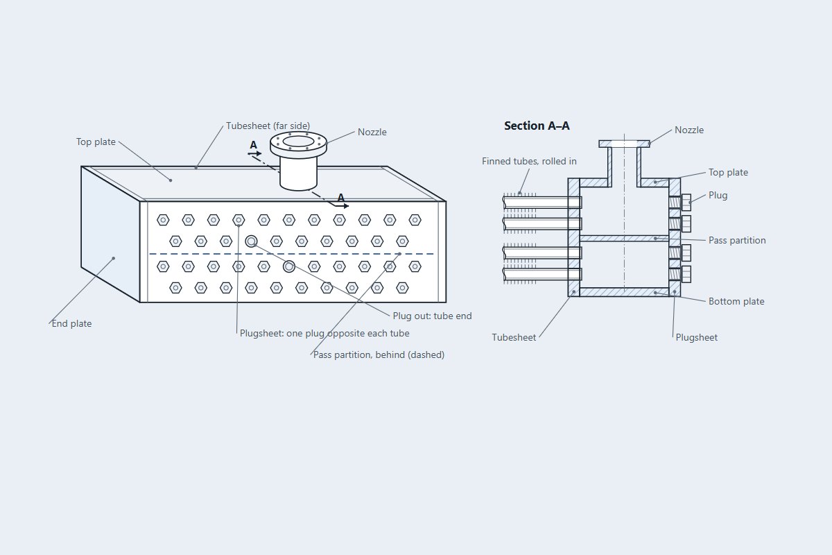
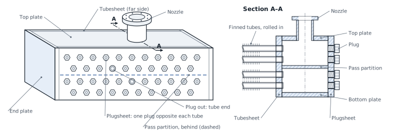
A plug header is a rectangular box, so it carries pressure mainly by bending, not by membrane stress as a cylinder does. ASME Section VIII Division 1, Mandatory Appendix 13 checks it as a frame of flat plates: a membrane stress and a bending stress at each location, the holes in the tubesheet and plugsheet as ligament efficiencies, and the end plates by UG-34.
This post follows that check on the header card, with numbers from the published and reference cases the engine is tested against.
Why a box is not a cylinder
Cut the box across its length and take a strip of unit width. The pressure on one pair of plates is carried as tension in the other pair, half in each: that is the membrane stress, and it does not depend on any stiffness. Each plate also bends as a beam between its corners, with end moments set by how the corners rotate. The bending grows with the square of the span over the thickness, the membrane only with the span over the thickness.
The sketches and the limits
The engine covers Fig 13-2(a) sketches (1) to (4) and the stayed sketches (7) to (10). Sketch (1), opposite sides equal, is the usual plug header with tubesheet and plugsheet of equal thickness; sketch (2) takes them unequal; sketch (3) has rounded corners; sketch (4) adds welded-on reinforcing frames. Each location gives a membrane row and a bending row on each fibre, and each is compared with its own allowable.
The equations assume a long box. For a length-to-span ratio from 1 to 2 the engine applies the short-box factors J2 and J3 of Table 13-18(b) to sketches (1) and (2); below 1 it refuses and asks for the largest dimension as the length.
Tube holes and plug holes (13-6)
The holes remove metal from the same section that carries the membrane force and the bending. 13-6 gives two efficiencies for a row of holes with several diameters through the thickness, such as a plug hole with a counterbore: em for membrane, from the mean hole diameter, and eb for bending, from the second moment of the drilled section.
When both are below the joint efficiency E, the net stresses Sm/em and Sb/eb are checked with E = 1.0 (13-4(g)). When both are at or above it, the gross stresses are checked with E. The code is silent when one is below and one above; the engine checks both readings and keeps the worse.
End plates, stays, MAWP and the test
The welded end plates are not part of the frame. 13-4(f) sends them to UG-34 with C = 0.20. A pass partition welded to the tubesheet and plugsheet acts as a stay; the stayed sketches (7) and (8) of 13-9 cover one partition or two at the third points.
For sketches (1) to (3) every stress is proportional to pressure, so the MAWP follows exactly from the worst ratio of allowable to stress, then the lower of that and the end plate. Sketch (4) is not linear and is solved by bisection. 13-16 sends the test to UG-99(b) and UG-100: the engine takes 1.3 times MAWP times the lowest stress ratio for hydrostatic, recomputes the stresses on the new geometry with the static head, and by default allows 0.9·Sy on membrane and 1.5 times that on membrane plus bending.
The shell model beside it
The header card can also build a shell model of the same box and read membrane and bending at the same locations. It never changes the code verdict. It compares against Appendix 13 evaluated at the model's own mid-surface spans, which are longer than the inside spans: on the PTB-4 box that alone raises the corner bending by 20.8 %. At that basis the corner converges to within 0.11 % on refinement.
Where it stops
- 01Nozzle and support loads on the header are not checked here; run a header nozzle on the Nozzle loads card.
- 02Sketches (5) and (6), obround and elliptical shells and external pressure are not covered.
- 03Hole rows on the reinforced plates of sketch (4), rows on a corner arc, stay-plate welds and a partition with a pressure difference across it are refused or not checked.
- 04Temperature differences and fatigue are not in the check or the model.
- 05The shell model is early access and under verification; it is a diagnostic beside the code check.
Try it in FEXLA
The Air-cooler header box card runs the Appendix 13 check for plug and cover-plate headers, with ligaments, end plates, stays, MAWP and the test, and the shell model beside it.
Open the cardReferences
- ASME Section VIII Division 1 (2023), Mandatory Appendix 13: 13-4(b), 13-4(f), 13-4(g), 13-6, 13-7, 13-8, 13-9, 13-16, Fig 13-2(a), Table 13-18(b).
- ASME Section VIII Division 1: UG-34, UG-99(b), UG-100.
- ASME PTB-4, example E4.12.1.
Method notes this draws on
Next post: WRC 537 or a shell model for a nozzle: how to choose
Educational article. It explains principles and is not design guidance; follow your governing code and edition.