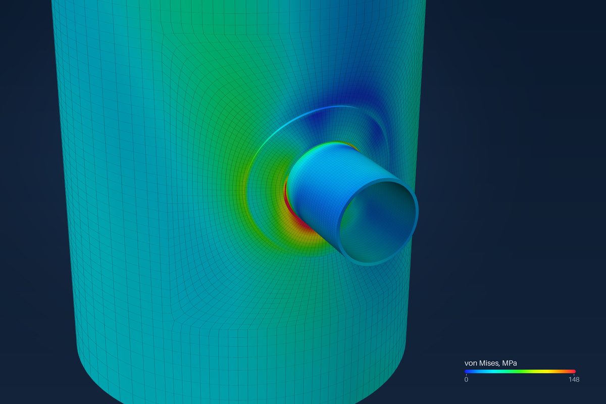
Run WRC 537 first whenever the bulletin covers the nozzle: it takes seconds, gives the same number every time and can be checked by hand. Move to a shell model when the calculator marks one as required, when it marks one as suggested and the result is close to the limit, or when the job needs an answer WRC 537 does not give.
The limits themselves are listed in the post on where WRC 537 stops. This post is about the decision: what each flag means for the job in hand, what the second route costs, and how to carry a nozzle across.
Start from what the calculator says
The results screen sorts its own warnings. A shell model is required when the bulletin does not cover the case at all, such as a shell thinner than the curves (γ above 300), an attachment closer than 0.5·Rm to the end of the cylinder, or a nozzle in the head knuckle. A shell model is suggested when WRC 537 still gives a number, but only by reading a curve at its edge. When neither appears, the bulletin covers the case and its answer stands.
| What the results screen shows | What it means | What to do |
|---|---|---|
| No flag | Inside the bulletin's range | Use the WRC 537 result |
| Suggested, ratio well below 1 | A curve read at its edge, with margin | WRC 537 is usually enough; record the warning |
| Suggested, ratio near or above 1 | The answer rests on the edge reading | Check it with the shell model |
| Required | Outside the bulletin | Do not use the WRC 537 number; build the shell model |
The middle rows need judgement, and the calculator gives one rule of its own. For a clip sized by an equivalent rectangle, it suggests the shell model once the stress ratio reaches 0.7, because the size itself is approximate. The same thinking fits any suggested flag: the closer the ratio is to 1, the less an edge reading should be trusted.
What each route costs
| WRC 537 calculator | Shell model | |
|---|---|---|
| Inputs | Shell, nozzle, pad, pressure, one load set | The same, plus the load rows, model length and nozzle projection |
| Run time | Seconds | Seconds in the browser, in our studies; minutes for a brick submodel |
| Size | No mesh | Browser solve up to 40 000 elements |
| Checking | Every curve reading printed, repeatable by hand | Mesh-quality checks; results compared with reference solutions |
| Status | Complete | Early access, under verification |
The real cost of the shell model is not the run. It is the extra inputs, the time to read a stress field instead of eight numbers, and the status of the result. The finite-element results are early access and under verification, so today they show where the governing stress is and how it compares, but they are not yet a source of design values.
Where WRC 537 is the right answer
- A round nozzle on a cylinder, a formed head or a cone, inside the charted γ and β.
- A nozzle that stands alone: no head, cone junction, seam or other attachment within about 2.5·√(Rm·T) of its edge.
- Loads given as one set, checked against the membrane and surface limits.
- A calculation that someone else must check line by line, because every coefficient can be traced to its figure.
For a nozzle that meets every line of this list, the shell model adds work without a better answer, and its status today adds a caveat that the WRC 537 result does not carry.
When a pass is not enough
A pass is only as good as the assumptions under it. Three cases deserve a second look even when the ratio is below 1. A nozzle with di/Di between about 0.25 and 0.6 is checked with Bijlaard's extended-range data, which the bulletin warns may be unconservative at the attachment edge. A nozzle on a cone is run as a cylinder of the local radius, and the result says it is approximate. And a nozzle near a neighbour is checked as if the neighbour were not there.
When a fail is not the end
A WRC 537 fail inside the bulletin's range is a real result, but it is not the only one available. The card's own note says the shell model is for the cases where WRC 537 stops or comes out too high. The shell model reports the stress in the nozzle and the pad as well as the shell, sorts the loads into sustained, operating and occasional rows, and offers a limit-load analysis. Each of those can show margin that a single elastic check of the shell cannot. Each is also early access, so a design that passes only on the shell model should be treated as unconfirmed until verification is finished.
Carrying the nozzle across
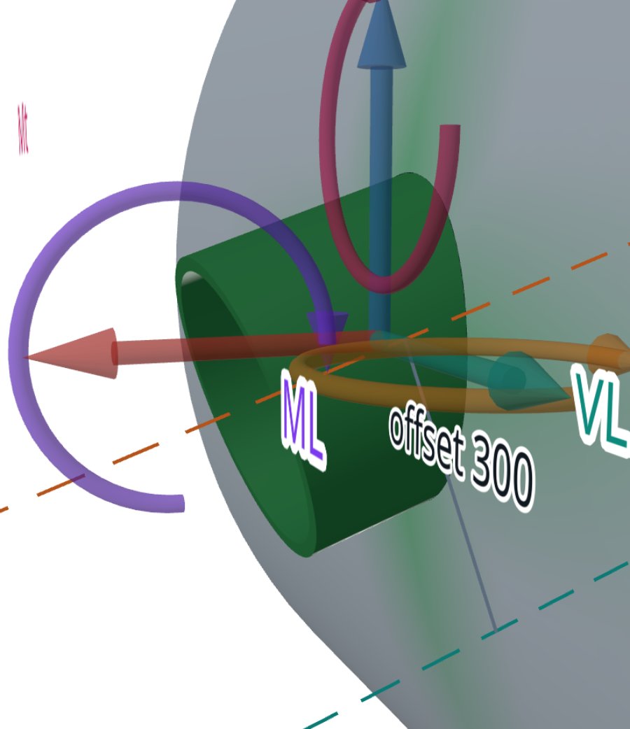
From the results screen the calculator offers to open the same nozzle in the shell model. The geometry, the design pressure, the design temperature and the allowable stresses come across. The loads do not, because the two tools do not yet use the same axes and signs. In the shell model the loads are typed again, in kN and kN·m, with P positive pulling the nozzle away from the shell. In the WRC 537 calculator P is positive inward, so the sign of P flips.
Where it stops
- 01Neither route sizes the opening reinforcement for pressure; take it from your vessel program.
- 02The handoff to the shell model carries no loads: they are entered again, with the sign of P reversed.
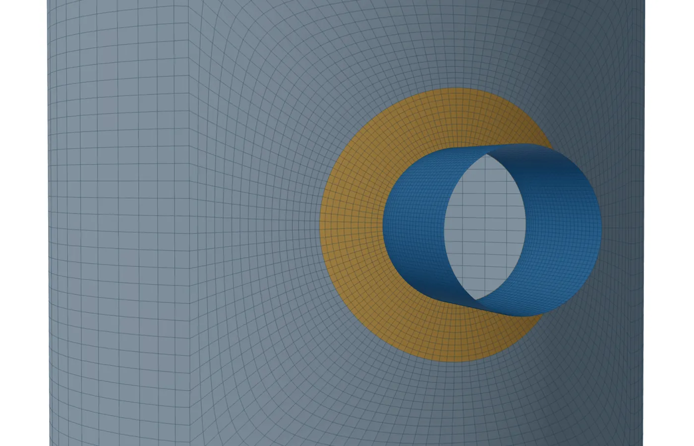
- 03The shell model is linear and bonded; a pad that is not welded all round, or parts that only touch, are not modelled.
- 04The finite-element results are early access and under verification. Until that is finished they are not a source of design values.
Try it in FEXLA
The Nozzle loads card runs WRC 537 first and offers the shell model of the same nozzle when the result calls for it.
Open the cardReferences
- WRC Bulletin 537, 4.5 Limits on application.
- ASME Section VIII Division 2, Part 5, Design by Analysis.
Method notes this draws on
Next post: WRC 107, WRC 297 and WRC 537: what changed, and what FEXLA uses
Educational article. It explains principles and is not design guidance; follow your governing code and edition.