
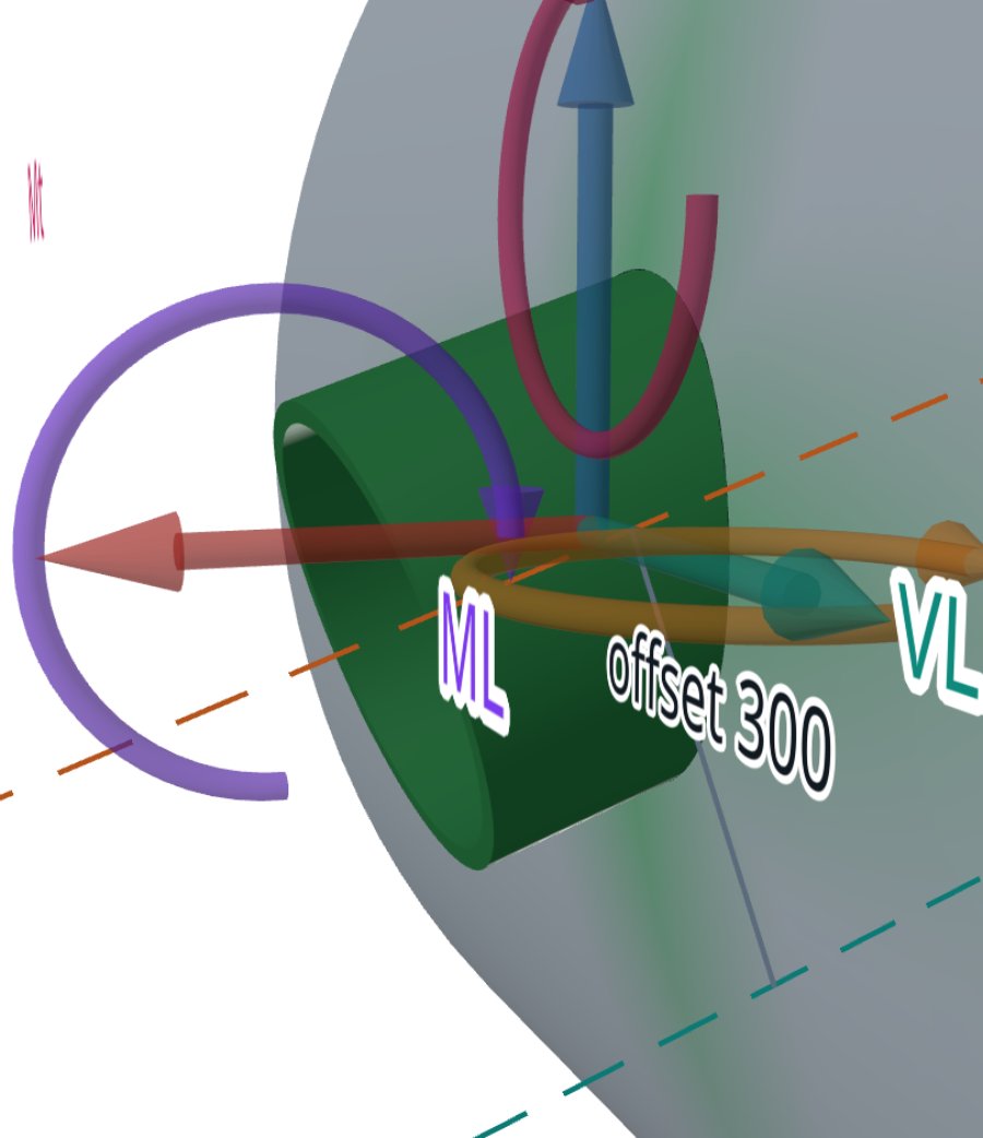
WRC 107 and WRC 537 carry the same theory, Bijlaard's solution for a rigid attachment on a cylinder or a sphere: WRC 107 published it as charts, and WRC 537 as equations as well as diagrams. WRC 297 is a different bulletin, and FEXLA does not use it.
This post keeps to what our method notes and the calculator's code support. It does not retell the bulletins' history, and it says where it cannot.
One theory, two forms
A load on a nozzle enters the shell over a small area, so the shell bends locally as well as stretching. Bijlaard solved this for a rigid attachment on a cylinder and on a sphere. The Welding Research Council published the results as charts in WRC 107. WRC 537, titled Precision Equations and Enhanced Diagrams, gives the same curves as equations.
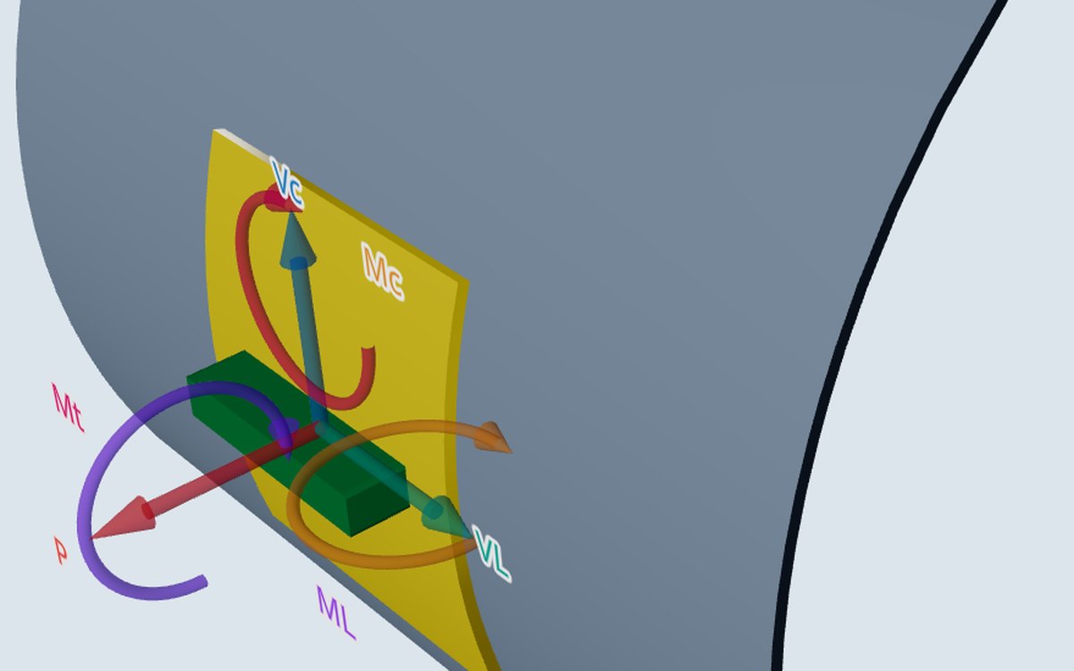
The method itself did not change. In both, each load gives dimensionless coefficients for membrane force and bending moment, read against the shell parameter γ = Rm/T and the attachment parameter β, and the stress is worked at four points round the attachment edge, on both surfaces.
What the equations change is how a value is read. A coefficient read off a printed chart depends on the reader and the scale. An equation gives every user the same value, and a program can show exactly how it got there.
What WRC 537 carries over from WRC 107
WRC 537 reprints the foreword to WRC 107, and that is where most of the limits come from. The calculator's warnings quote them.
- For cylinders, Bijlaard's theory is useful up to a nozzle-to-shell diameter ratio di/Di of about 0.25.
- The experiments the bulletin cites went to di/Di = 0.126 only.
- For larger openings Bijlaard supplied extended-range data, at β of 0.375 and 0.50 and di/Di approaching 0.60, with his own warning that at the attachment edge they may be unconservative.
- Appendix A.3 of WRC 537 found errors in that extended data, and the bulletin adjusted those curves toward the safe side.
- For spheres, the shallow-shell theory limits the opening to about a third of the shell diameter for thin shells, less for thicker ones (Appendix A.2, Figure A-1). Tests were at about 0.10.
WRC 537 also states limits of its own in 4.5: the cylinder must be at least as long as its mean radius, and the attachment at least 0.5·Rm from the end. The calculator treats both as cases the bulletin does not cover.
What the calculator implements
| Part of WRC 537 | In the calculator |
|---|---|
| Cylinder figures 1A to 4A, 1B-1 to 4B, 1C to 4C (14 in all) | Each held as ten coefficients at each tabulated γ |
| γ from 5 to 300 | Coefficients interpolated linearly in γ, held at the ends |
| β up to 0.5 | A ratio of polynomials evaluated at β; values above 0.5 read at 0.5 |
| Curves that end before β = 0.5 (1C, 2C) | Held at their end value, not extended |
| Kθ factors for a round attachment | Read against γ and applied to the bending from the moments |
| Shear and torsion on a round attachment | V/(π·r₀·T) and MT/(2π·r₀²·T) |
| Sphere curves, for a nozzle on a formed head | A separate path, with its limit checked against Figure A-1 |
The report prints each interpolation with the figure it came from, the γ values either side and the coefficients used. A checker with the bulletin can repeat any line.
Where WRC 297 stands
Our notes record WRC 297 as the bulletin that also treats stresses on the nozzle side and larger openings. FEXLA does not implement it, does not quote it in any warning, and does not adjust any WRC 537 value toward it. No other bulletin is part of the calculator.
Two things cover the gap in part. The calculator checks the nozzle neck as a thin tube under pressure, axial load, bending, shear and torsion, against the nozzle's own allowable. Where the stress in the nozzle wall near the junction matters, the shell model reports it directly.
Comparing with an older calculation
An older calculation made from the WRC 107 charts uses the same theory, so the stress pattern and the points checked are the same. The numbers may differ where a coefficient was read by eye, or where a value lay off the chart. Comparing the two line by line, coefficient by coefficient, shows which it is.
Where it stops
- 01WRC 297 is not implemented; the neck is checked as a thin tube, and the shell model gives nozzle-wall stresses.
- 02The calculator applies WRC 537 only inside the limits the bulletin states, and flags or refuses the rest.
- 03Edition differences between printings of the bulletins are not covered here.
- 04The shell model's results are early access and under verification.
Try it in FEXLA
The Nozzle loads card runs the WRC 537 check on a cylinder, a formed head or a cone and prints every curve reading in the report.
Open the cardReferences
- WRC Bulletin 107: Local Stresses in Spherical and Cylindrical Shells due to External Loadings.
- WRC Bulletin 537: Precision Equations and Enhanced Diagrams for Local Stresses in Spherical and Cylindrical Shells due to External Loadings; 4.5, Appendix A.2, Appendix A.3.
Method notes this draws on
Next post: The six nozzle load components P, VC, VL, MC, ML, MT and their signs
Educational article. It explains principles and is not design guidance; follow your governing code and edition.