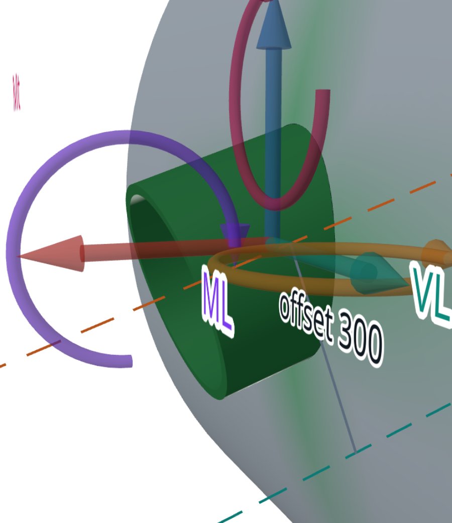
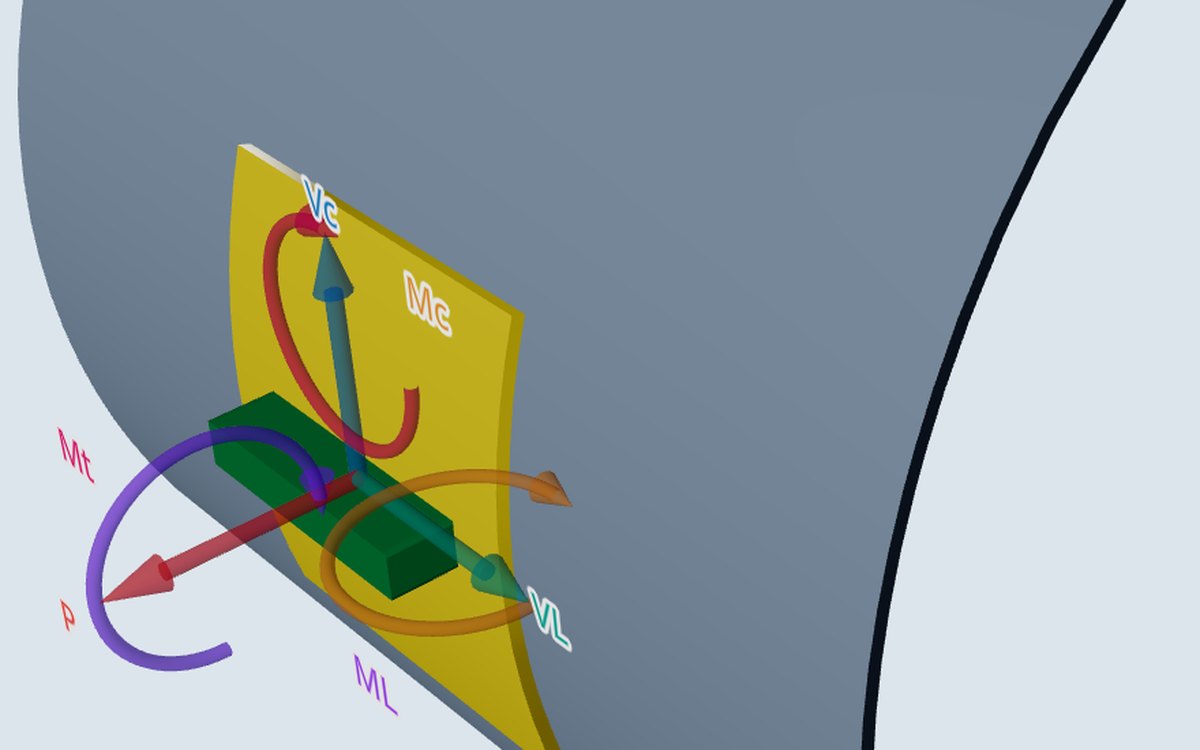
A nozzle load table gives six numbers at the nozzle-to-shell junction: the radial force P, the shears VC and VL, the bending moments MC and ML, and the torsion MT. In the WRC 537 calculator P is positive pushing the nozzle into the shell, a positive ML presses the shell in on the A side, and a positive MC presses it in on the C side.
This post sets out the axes, the positive senses and what each component does at the four points the bulletin checks, so a load from any source can be entered with the right sign.
The axes at the junction
The calculator's frame sits at the junction, on the nozzle axis. One axis runs along the vessel (longitudinal), one round it (circumferential), and one along the nozzle into the shell (radial). A and B are the two points on the nozzle edge on the longitudinal line, C and D the two on the circumferential line. Each is checked on the outer and the inner surface, eight points in all.
| Load | Acts | Positive sense in the calculator |
|---|---|---|
| P | Along the nozzle axis | Inward, toward the vessel axis |
| VL | Along the vessel | Toward B |
| VC | Round the vessel | Toward C |
| ML | Bends the nozzle in the longitudinal plane | Presses the shell in on the A side |
| MC | Bends the nozzle in the circumferential plane | Presses the shell in on the C side |
| MT | Twists the nozzle about its own axis | Right-hand rule about the radial axis |
P: the radial load
The radial load pushes or pulls the shell wall under the whole nozzle, so it stresses all four points. A positive, inward P gives compressive membrane stress at A, B, C and D; the bending part has one sign on the outer surface and the other on the inner. A and B see the same stress from P, and so do C and D.
This is the sign that matters most. Reversing P changes the membrane stress at every point at once, and pressure adds tension there, so a P that pulls outward can govern when one that pushes does not. A connected line that pushes the nozzle into the vessel gives a positive P here.
ML and MC: the bending moments
A moment rocks the nozzle. ML rocks it along the vessel and stresses A and B only: a positive ML puts compression at A and the same magnitude of tension at B, in membrane and in bending. MC rocks it round the vessel and does the same at C and D, compression at C and tension at D.
Because A and B see the same stress from P, reversing ML only swaps the two points, and both are checked; the worst normal stress is the same either way. The same holds for MC at C and D. What the sign can change is the shear stress that goes with each point, below.
VC, VL and MT: shear stress
The shears and the torsion give shear stress in the shell round the nozzle, not membrane or bending stress. On a round nozzle:
- VC, the circumferential shear, gives its shear stress at A and B, with one sign at A and the other at B.
- VL, the longitudinal shear, does the same at C and D.
- MT gives the same shear stress at all eight points.
So at one of each pair the shear from VC or VL adds to the torsion, and at the other it subtracts. On a rectangular clip WRC 537 gives no stress for torsion, and the calculator records MT there without using it.
Loads at the nozzle end
WRC 537 defines the loads at the junction. If the table gives them at the flange face instead, the calculator carries them down the nozzle: a shear at the end adds a moment at the junction equal to the shear times the length. With the senses above, that is:
P, MT and the shears do not change. On a formed head the calculator names the loads P, V1, V2, M1, M2 and MT; M2 pairs with V1 the way ML pairs with VL, and M1 with V2 the way MC pairs with VC.
Loads from another frame
Loads from a line stress analysis may come in global axes. The shell model in FEXLA can take them that way, or in its own frame: an axis out along the nozzle, the vessel axis made square to it, and the third by the right-hand rule. In the shell model P is positive pulling the nozzle away from the shell, the opposite of the WRC 537 calculator, and loads are in kN and kN·m. The two tools do not yet share one convention, so a load set moved between them must be converted by hand, starting with the sign of P.
Where it stops
- 01The calculator takes loads in its own junction frame only; global loads must be resolved into P, VL, VC, ML, MC and MT first.
- 02Stress is computed at A, B, C and D only; nothing between the points is checked.
- 03On a rectangular clip, torsion gives no stress in WRC 537.
- 04The shell model uses a different sign for P, and its results are early access and under verification.
Try it in FEXLA
The Nozzle loads card takes the six loads at the junction or the nozzle end and can show the load directions it uses beside the inputs.
Open the cardReferences
- WRC Bulletin 537: Precision Equations and Enhanced Diagrams for Local Stresses in Spherical and Cylindrical Shells due to External Loadings; Figure 2 load convention.
Method notes this draws on
Next post: How a reinforcing pad changes nozzle stress under external loads
Educational article. It explains principles and is not design guidance; follow your governing code and edition.