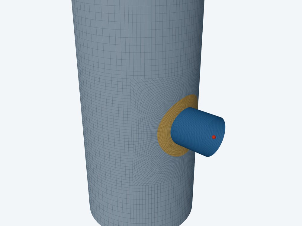
A reinforcing pad lowers the shell stress at the nozzle, because the wall there is thicker. It also makes a second edge, where the pad stops and the shell is back to its own thickness, and that edge can govern. WRC 537 is run twice, once at each edge, and the larger result counts.
This post follows how the calculator sets up the two checks, what the pad's width and thickness change, and what a shell model shows that the bulletin cannot.
Two edges, two checks
The bulletin knows one attachment on one plain shell. A padded nozzle is two such problems, one inside the other, and the calculator sets up each one in turn.
- At the nozzle edge the attachment is the nozzle and the shell is the shell plus the pad. The thickness is T = t + t_pad − CA, so γ = Rm/T is smaller. The nozzle radius r₀ is unchanged.
- At the pad edge the attachment is the pad and the shell is the shell alone, T = t − CA. The attachment radius is the pad's own, r₀ = pad OD/2 − CA, so β = 0.875·r₀/Rm is larger.
Each edge goes through the full method: the curve coefficients for every load, the stress at the four points on both surfaces, the pressure stress, then the limits 1.5S and 3S. The report prints both sets side by side, and the pass or fail takes the worse of the two. At the pad edge only shell metal is present, so only the shell's allowable stress applies there.
The parameters at each edge
The two edges trade against each other. A thicker pad lowers the stress at the nozzle edge but leaves the pad edge where it was. A wider pad moves the pad edge out and enlarges β there, which spreads the load over more shell. Once the pad-edge β passes 0.5 the curves stop, the values are read at 0.5, and the result says so.
How wide a pad counts
Width does not help without limit. For the pressure part of the check, the calculator works out the stress intensity factor of ASME Section VIII Division 2, 4.5.5, and there the shell and pad count only within a reinforcement length along the wall:
Past that length, extra pad width adds weight and welding but nothing to the pressure check. For the external loads the useful width is set by the decay length √(R·t): local bending under the nozzle dies out over a few of them, and a pad that reaches well past that zone mostly sits on shell that was never highly stressed.
The load still passes through the nozzle
A pad makes the shell stiffer at the junction. The nozzle loads are the same, so the same moment and force still pass from the nozzle wall into the shell. WRC 537 reports the shell only. The calculator adds a separate check of the neck as a thin tube, with the same junction loads, against the nozzle's allowable stress Sn for longitudinal stress and 0.7·Sn for shear. That check takes no account of the pad.
With a thick pad on a thin nozzle the governing stress can move from the shell into the nozzle wall next to the weld. The bulletin cannot show this. It is one of the reasons the method notes give for moving to a shell model: stresses wanted in the nozzle or the pad, not only in the shell.
What the shell model adds
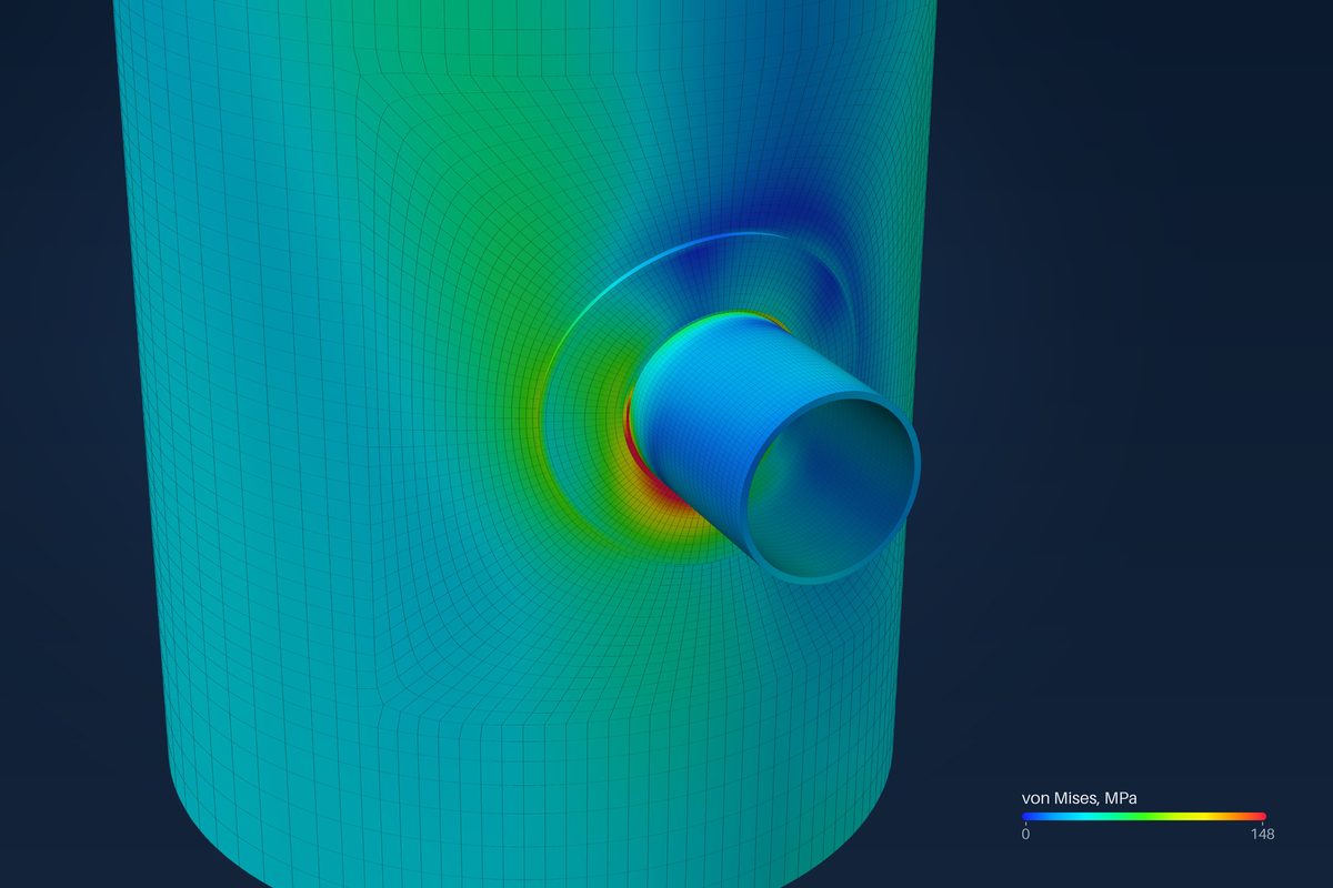
In the shell model the pad is integral with the shell: the elements under it carry the shell thickness plus the pad thickness, on the shell's mid-surface. The pad edge is a step in section, which is where its own stress concentration comes from. The mesh runs in rings to the nozzle intersection and to the pad edge, so both edges are refined.
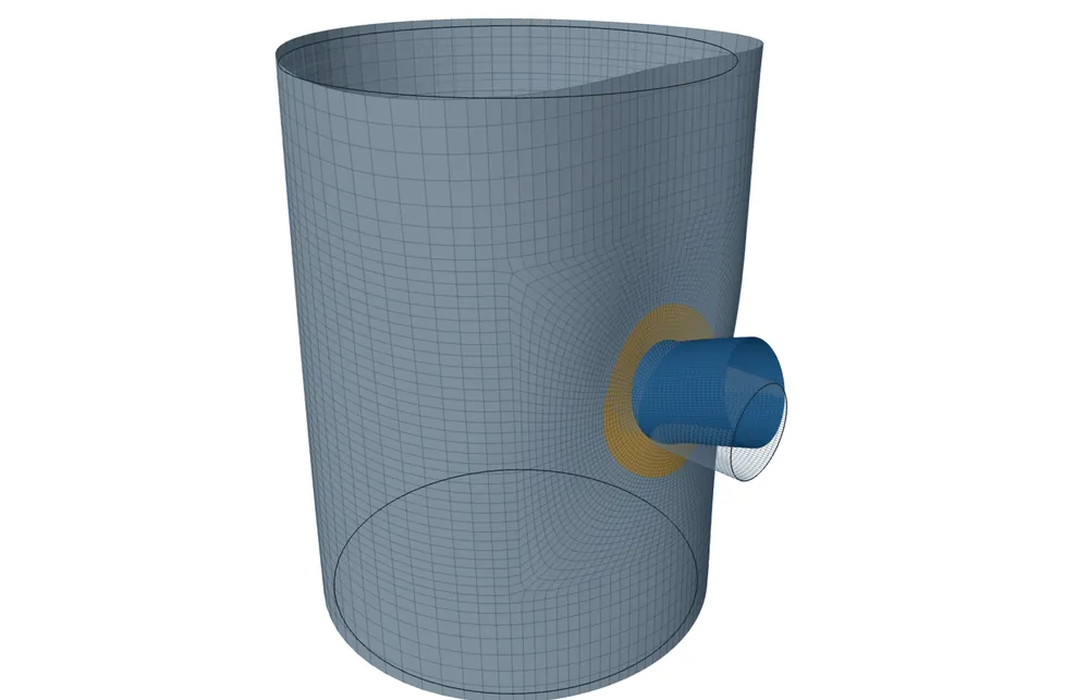
The model is bonded and linear. A pad welded all round behaves that way. A pad that only touches the shell between its welds, or has a weep hole and a gap under it, would need contact, which is not modelled.
Where it stops
- 01The calculator does not check that the pad fits on the shell: a pad crossing a seam, a course joint or a head knuckle is for the engineer to confirm. On a head with its full shape given, the spherical-region check uses the pad's diameter.
- 02The pad edge of a round nozzle on a cylinder follows the same rule as the clip and the head nozzle, and has not yet been checked against an independent worked case.
- 03The calculator and the shell model do not yet take corrosion off the pad the same way: the calculator corrodes it, the shell model does not. An alignment is planned.
- 04Pads that are not welded all round, and parts that only touch, are not modelled.
- 05The finite-element results are early access and under verification. Until that is finished they are not a source of design values.
Try it in FEXLA
The Nozzle loads card runs WRC 537 at the nozzle edge and at the pad edge, adds the neck check, and opens the same nozzle as a shell model.
Open the cardReferences
- WRC Bulletin 537: Precision Equations and Enhanced Diagrams for Local Stresses in Spherical and Cylindrical Shells due to External Loadings.
- ASME Section VIII Division 2, 4.5.5 (radial nozzle in a cylindrical shell) and Part 5 stress categories.
Method notes this draws on
Next post: Hillside and tangential nozzles: what WRC 537 covers
Educational article. It explains principles and is not design guidance; follow your governing code and edition.