
WRC 537 is written for a radial nozzle, whose axis passes through the shell axis. A hillside nozzle, offset from that axis but parallel to the radial direction, stays in the calculator: the load stresses are worked as for a radial nozzle of the same diameter, and only the pressure stress factor grows. A tangential nozzle, or one tilted at a free angle, is outside the bulletin and goes to the shell model.
The line between the two is not a matter of taste. It comes from what the bulletin's shell theory can still describe.
Why a hillside nozzle can stay in WRC 537
Cut a round tube through a flat surface at an angle θ from the normal and the hole is an ellipse. Its short axis is the tube diameter d whatever the angle; its long axis is d/cos θ. The usual conservative practice for a non-radial nozzle is to take the short axis, the shortest chord, as the size of an equivalent round attachment. That is the same size as the radial nozzle, so the calculator uses the same r₀ and the same β, and the curve coefficients do not change.
This rests on the flat-tangent-plane picture that the bulletin's shallow-shell theory uses throughout. It holds well for a small offset and grows less reliable as the angle grows. No safe tilt limit has been sourced, so the calculator states the assumption in the report and does not invent one.
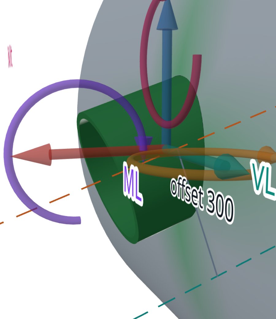
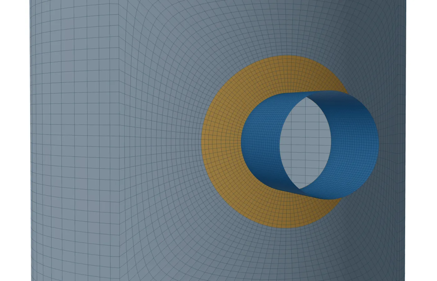
What the offset changes: the pressure factor
Where a hillside nozzle differs is the pressure stress at its edge. The opening cut in the shell is longer round the circumference than the nozzle is wide, so pressure acts on a larger area. The calculator works the pressure stress intensity factor I of ASME Section VIII Division 2 with that longer cut.
- On a cylinder, the nozzle is entered with its offset from the shell axis. The radius used in the pressure force is half the arc length of the opening in the circumferential plane, never less than the nozzle radius (4.5.6).
- On a formed head, the nozzle is entered as hillside (axis parallel to the vessel axis, away from the pole) or perpendicular (axis square to the vessel axis). The radius used is Rₙ/cos θ or Rₙ/sin θ (4.5.11).
- A head nozzle marked tilted without saying which gets the radial factor, with a note: a non-radial head nozzle can have a factor up to about a third higher.
What the calculator refuses
Three cases are refused with a message that names the shell model. A nozzle inclined at a free angle in a shell or head. An offset or tilted nozzle on a cone, where only a radial nozzle or one along the cone's own axis is taken. And a tangential nozzle, whose axis runs along the shell's surface rather than into it.
The tangential case shows plainly why. As the angle from the normal approaches 90°, the long axis d/cos θ grows without limit. The model's own geometry has stopped describing the junction: the nozzle no longer pierces a nearly flat patch of shell, it runs along a curved one. That is a sign the shallow-shell assumption has failed, not a real result.
What the shell model does instead
The shell model builds the nozzle along its real axis and meshes the real intersection curve with the shell. The orientations it takes are radial, offset (hillside), tangential, angled, tilted in any direction, and on heads parallel or perpendicular to the vessel axis.
| Nozzle | WRC 537 in the calculator | Shell model |
|---|---|---|
| Radial, cylinder, head or cone | Yes | Yes |
| Hillside on a cylinder | Yes, larger pressure factor | Yes |
| Hillside or perpendicular on a head | Yes, larger pressure factor | Yes |
| Tilted at a free angle | Refused | Yes, under 75° |
| Tangential | Refused | Cylinder or cone, round only |
| Offset on a flat plate | Not offered | Refused: move the nozzle instead |
A tangential nozzle is placed so its outside wall lines up with the shell's inside surface, on either side. It must be round, and its outside radius must be smaller than the shell's inside radius. The optional solid detail at the junction does not take tangential nozzles or tilts over 50°.
Where it stops
- 01The calculator takes no tilt angle: the hillside result rests on the shortest-chord convention and the shallow-shell picture, and is less reliable as the offset grows.
- 02The hand-over to the shell model carries the geometry, not the loads, because the two tools set their load axes differently today. Enter the loads again in the shell model's axes.
- 03Opening reinforcement for pressure is not sized here; take it from your vessel program.
- 04The finite-element results are early access and under verification. Until that is finished they are not a source of design values.
Try it in FEXLA
The Nozzle loads card takes a radial or hillside nozzle on a cylinder and a round nozzle on a head or cone, and opens the shell model for the rest.
Open the cardReferences
- WRC Bulletin 537: Precision Equations and Enhanced Diagrams for Local Stresses in Spherical and Cylindrical Shells due to External Loadings.
- ASME Section VIII Division 2, 4.5.6 (hillside nozzle in a cylinder), 4.5.10 and 4.5.11 (radial and non-radial nozzles in formed heads).
Method notes this draws on
Next post: Large openings beyond UG-36(b): why the rules stop and what replaces them
Educational article. It explains principles and is not design guidance; follow your governing code and edition.