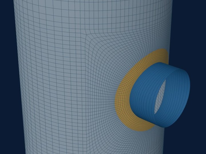
Division 1 sets size limits on openings in UG-36(b), and a larger opening is sent to Appendix 1-7. WRC 537 has its own limit: its cylinder theory holds to a nozzle-to-shell diameter ratio of about 0.25, and no curve goes past β = 0.5. Past either limit, a shell model of the real nozzle and shell gives the stresses instead.
Both limits come from the same assumption: the hole is small next to the shell. This post explains what breaks when it is not, and what the calculator and the shell model do about it.
What the size limits mean
The opening rules for pressure, area replacement in Division 1 and its counterpart in Division 2, put back near the hole the wall that the hole took away. That balance is worked in membrane terms. It works when the shell round a small hole stays nearly round, so the stress it has to carry is close to the plain-shell membrane stress and the bending at the edge stays local.
A large hole breaks that. The shell next to it is no longer stiffened by shell on all sides, it flattens and ovals under pressure and under the nozzle loads, and bending at the edge becomes a large part of the stress. The size limits mark where the code no longer trusts the simple rule on its own. Past them, extra rules or a design-by-analysis route apply.
Division 2 is explicit for one case. Its opening rules for external pressure and axial compression, 4.5.17.1, apply only to openings up to 25 % of the cylinder diameter and 80 % of the ring spacing. Larger ones are to be designed by Part 5. The skirt opening job checks the 25 % diameter limit and flags an opening beyond it; the nozzle shell model does not yet print that flag.
Why the bulletin stops
WRC 537 rests on Bijlaard's theory, which treats the attachment as a load spread over a patch of an otherwise complete shell. The bulletin says that theory is useful for cylinders up to a diameter ratio of about 0.25. The tests it cites went to 0.126. For larger nozzles Bijlaard gave extended-range data, which the bulletin adjusted toward the safe side after tests found errors in it. The calculator keeps track of where a nozzle falls:
| di/Di (inside diameters) | What the calculator says |
|---|---|
| Up to 0.25 | Nothing: inside the theory's stated range. |
| 0.25 to about 0.6 | Extended-range data, adjusted toward the safe side but possibly unconservative at the edge, with little test support. Approximate; a shell model is advised. |
| Above 0.6 | No supporting data in the bulletin. Indicative only; use a shell model. |
| β above 0.5 at any ratio | The curves stop; values are read at β = 0.5 and the result says so. |
Opening reinforcement for pressure is not sized in the calculator. It adds the pressure stress at the nozzle edge through the stress intensity factor of Division 2, but the area check itself belongs to the vessel calculation.
How the shell model handles a large opening
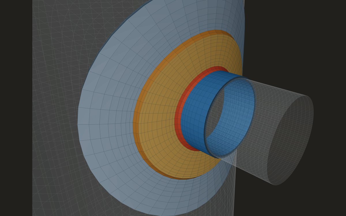
The shell model has no size limit in its theory. The nozzle and shell are meshed along their mid-surfaces and joined along the exact intersection curve, which on a large nozzle is a strongly saddle-shaped line. Rings of elements run in to that curve and to the pad edge. The element size follows the decay length √(R·t), so a thin shell gets fine elements where its bending dies out.
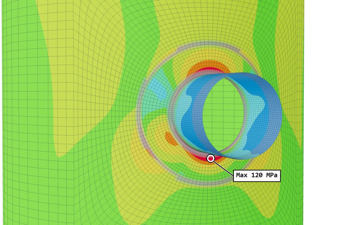
Shell elements report membrane force and bending moment per unit length, so the membrane and bending split of Division 2, Part 5 comes out directly. The model reports the nozzle and the pad as well as the shell. Where the elastic check fails by a small margin, a limit-load analysis of the same model can show the real margin, since a large opening often has more capacity than the elastic split suggests.
A large opening reaches further
Local bending at a junction dies out within about 2.5 decay lengths. A large opening also ovals the shell, and ovalisation fades only over about Rm·√(Rm/t), which is many decay lengths on a thin shell. In our studies, at 2.5√(Rm·t) from the junction the opening still lowered the hoop stress by 1 to 3 % at d/D 0.1, and by up to 17 % at d/D 0.8 on a shell with D/t of 500.
This matters for how long the model is. Today the shell is cut at the largest of 4√(Rm·t), one nozzle diameter and one shell radius on each side. In our studies that length held a thin shell round too close to a large nozzle: under a circumferential moment or a radial force the junction stress came out too low against a longer model, by up to about 47 %, and under a longitudinal moment too high. A longer default length is being tested and is not yet released. Until then, for a large nozzle on a thin shell, enter the real distance to the heads or rings.
Where it stops
- 01The size limits of UG-36(b) and the rules of Appendix 1-7 are not worked here; they belong to the vessel calculation.
- 02The 4.5.17.1 flag is printed by the skirt opening job only, and only against the 25 % diameter limit.
- 03The shell model's automatic length can be too short for a large nozzle on a thin shell; give the real span.
- 04Peak stress at the weld toe needs a solid model or a fatigue method; a shell model does not resolve it.
- 05The finite-element results are early access and under verification. Until that is finished they are not a source of design values.
Try it in FEXLA
The Nozzle loads card runs WRC 537 and flags a large nozzle; the same case then opens as a shell model of the real opening.
Open the cardReferences
- ASME Section VIII Division 1, UG-36(b) and Mandatory Appendix 1-7.
- ASME Section VIII Division 2, 4.5.17.1 and Part 5, Design by Analysis.
- WRC Bulletin 537, Appendix A.3 and the Foreword to WRC 107 as reprinted in it.
Method notes this draws on
Next post: Obround and tombstone openings: how they are analysed
Educational article. It explains principles and is not design guidance; follow your governing code and edition.