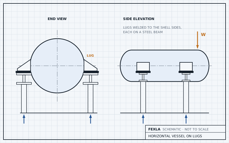
A horizontal vessel on four support lugs is statically indeterminate: statics fixes the totals, but how the load splits between the lugs, and how hard each one pushes on the shell, depends on how stiff the shell is between them. A lug on a horizontal vessel also carries the weight across the shell rather than along it, which is not the case WRC 537 or Zick's method was written for. So the tool models the whole vessel, heads and lugs included, reports each lug's reaction, and sizes the lug's own plates and weld by hand beside the model.
This post covers what statics settles, what it does not, what the model holds, and what the hand check of the lug adds.
What statics settles
Take two stations along the vessel, each with two lugs on the vessel's sides, one either side. For weight alone, the split between the stations follows from moments about one of them. The split between the two lugs of a station follows from symmetry.
What statics leaves open
- A lug on the side, at ±90° from the bottom, stands out horizontally. The weight reaches it as a vertical force some distance out from the shell, so the lug hands the shell a shear and a moment, and the moment bends the shell round the lug. How much the two lugs of a station also push in or pull out depends on the stiffness of the shell ring between them, of the lugs, and of the steel they rest on.
- Under a transverse load, wind or seismic across the vessel, the two lugs of a station share it by stiffness, not by any rule of statics.
- Along the axis, one station is usually free to slide. Which station takes the longitudinal load, and how the shell between them carries it, follows from that choice.
- If the supports or the loads are not symmetric, the four reactions are no longer fixed by statics at all.
That is why a hand split taken as a quarter of the weight per lug can be right for the vertical part and still miss what bends the shell: the moment from the load's offset, and any push across the ring.
WRC 537 on each lug does not settle it either. The bulletin's footprint approach for a support, with its long side along the shell axis, assumes the load plane of a vertical vessel, where the support carries weight along the shell. On a horizontal vessel the lug carries the weight across the shell and round it. Zick's method is for saddles, not lugs. Hence one model of the whole vessel.
The whole-vessel model
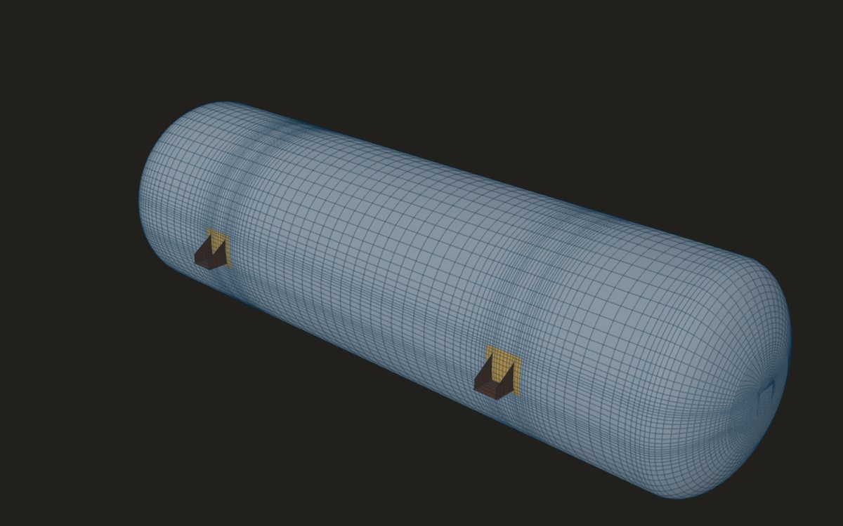
- The cylinder between two heads, ellipsoidal, torispherical or hemispherical, as one shell mesh.
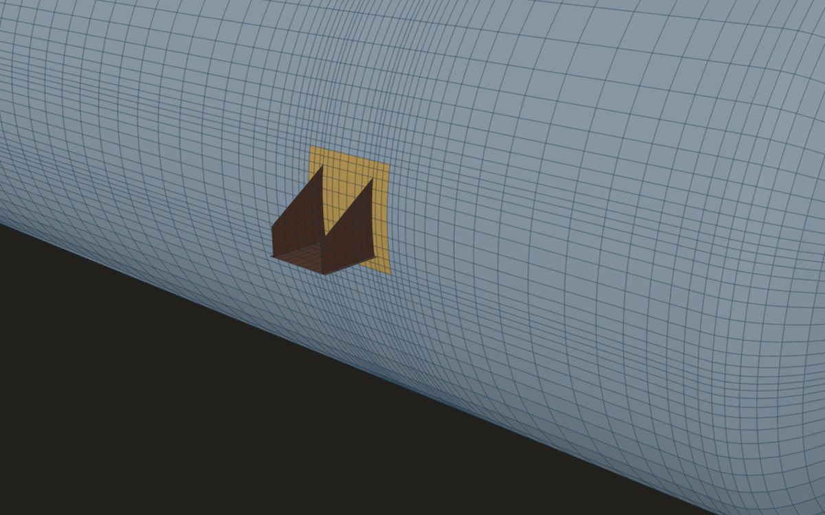
- One support lug at every station and azimuth, on the vessel's sides (30° to 150° from the bottom, ±90° by default), with or without a pad: a base plate along the axis on the lug's lower side and one gusset (a tee) or two (a channel, web down) against the shell, the gussets tapering from their depth at the shell to a smaller depth at the tip.
- Each base plate held, pinned or fixed, over the width where it rests on the steel, with one station free to slide along the axis.
- Pressure; the metal's weight as a body load; the liquid by its hydrostatic pressure, empty, operating to its level, or full of test water; extra weight spread over the shell.
- Wind, seismic and longitudinal loads as resultants at the vessel's centre, spread over the shell.
The lug is given by its base plate (length along the axis, width out from the shell, thickness), its gussets (one or two, thickness, depth at the shell and at the tip, spacing), the bearing width on the steel, and the fillet weld to the shell. The plates are meshed with the shell and share its nodes at the weld. A pad thickens the shell wall under each lug. Stations are measured from the left tangent line and azimuths from the bottom of the vessel, so a pair at ±90° stands on the horizontal centre line, one each side.
What is reported
Each support's reaction is reported per combination, so the share is read off, not assumed. The shell within √(R·t) of a support's weld and the support plates within the same distance are junction zones, checked for local membrane and for local membrane plus bending plus secondary. The support plates beyond are general membrane. The shell between the supports is checked as the rest of the shell. There is no model cut: the whole vessel is in the model, so no stress is lost near a boundary.
The liquid condition matters for the share. A full vessel of test water is the heaviest case for the lugs, while the operating level changes where the liquid's weight sits along and round the shell.
The lug itself, by hand
The model gives the shell's stress round each lug. The lug's own plates and weld are sized by hand beside it, after Bednar's support-lug method, for the vertical load on one lug taken as the weights over the number of lugs. The model's reactions show how far each lug's real share is from that.
- Bearing: the load over the width the base plate rests on times its length gives the bearing pressure.
- Base plate: between two gussets, a plate held on three edges (the shell and the gussets) with its outer edge free, under that pressure (Roark Table 11.4 case 2a); beyond the gussets, or either side of a single gusset, a cantilever. Bending against 0.6·F_y.
- Gussets: each takes its share of the load as an eccentrically loaded plate along its sloping edge, against the allowable stress of a column of its own slenderness (AISC ASD), so a thin gusset is penalised twice.
- Weld, lug to shell: the gusset and base plate welds as lines, taking the shear and the moment of the load about the shell, against 0.3 of the electrode's tensile strength on the throat.
Where it stops
- 01Saddles are not covered: a saddle bears on the shell, which needs contact.
- 02One lug for every support, at every station and azimuth, on the vessel's sides only; both heads alike.
- 03The steel the lugs rest on is not meshed: each base plate is held over its bearing width (bonded, no contact), and the steel's own stress and bolts are not checked.
- 04The lug hand check takes an equal share of the weight per lug; the shell model is early access and under verification.
Try it in FEXLA
The Vessel on legs card builds a horizontal vessel on two or four support lugs as one shell model, reports each lug's reaction, and checks the lug's base plate, gussets and weld by hand beside it.
Open the cardReferences
- ASME Section VIII Division 2, Part 5 (stress categories and limits).
- WRC Bulletin 537 and Zick's method, for why they do not cover this case.
- Bednar, Pressure Vessel Design Handbook, 2nd ed., 5.2 Support lugs.
- Roark's Formulas for Stress and Strain, 7th ed., Table 11.4 case 2a.
- AISC Manual of Steel Construction, ASD, 9th ed., column allowable stress.
Method notes this draws on
Next post: Skirt access openings: tombstone against obround
Educational article. It explains principles and is not design guidance; follow your governing code and edition.