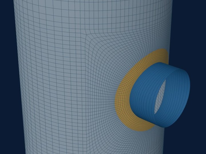
An insert plate replaces the shell round a nozzle with a thicker plate, butt welded into the shell, where a pad adds a plate on top of it. In the shell model the insert is a zone of the wall with its own thickness and offset, tapered where UW-9(c) needs it. Its outer edge is a second discontinuity, and the stress there is often the one that governs.
This post covers how the insert is built, what is read at its edge, and what the model does not credit.
Pad or insert
A pad is a second plate fillet welded over the shell. The shell model treats a pad as a thickened wall bonded to the shell all round. An insert is a single plate: the shell is cut out and the thicker plate is butt welded in, so the wall is one piece of metal of the insert's thickness.
That makes an insert a natural fit for a shell model. There is no question of whether two plates act together, and no weep hole or gap to ignore. What changes is the edge: a pad edge is a fillet weld on the shell, an insert edge is a butt weld between two plates of different thickness.
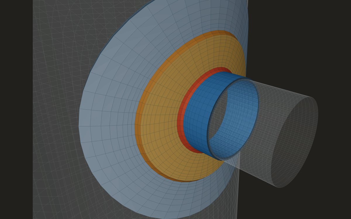
How the model builds it
- Round or rectangular, centred on the nozzle. A rectangular insert is offered on a cylinder, a cone or a rectangular flat plate.
- The insert replaces the wall over its outline, with its own thickness and an offset from its alignment: inside flush, outside flush or centred.
- Where the step to the shell passes the UW-9(c) trigger, a 3:1 taper is built on the insert side, inside its outline, as rows of stepped thickness.
- A round insert follows the ring of elements the mesher already uses for a round pad. A rectangular one keeps square corners on the grid.
- An insert is not combined with a pad or with gussets on the same nozzle.
- The insert takes the pad's material values from the Materials page.
The insert's edge is a second discontinuity
At the nozzle the thick insert carries the local bending well. At its edge the wall drops back to the shell thickness, and the load that the insert gathered has to pass into a thinner wall. The edge has its own bending zone, a few decay lengths √(R·t) wide on the thin side.
The model names the outline "Insert plate edge" and reads it as a weld line, as it reads a pad edge. Because the edge is a butt weld, no fillet leg is stepped off before the reading. The membrane plus bending stress there is checked against its allowable, and it is often higher than at the nozzle once the insert is thick.
If the insert is small, the nozzle zone and the edge zone overlap and the edge sees part of the nozzle's local bending as well. A wider insert keeps them apart, at the cost of more thick plate.
What the model does not credit
Opening reinforcement for pressure is a rule check of the vessel calculation: the area replacement of UG-37 or VIII-2 4.5. The shell model takes the insert as geometry only. It reports the stresses the insert gives, and takes no area credit. The report says so beside the insert's size.
WRC 537 has no insert plate. A WRC 537 check on the insert's thickness alone describes the nozzle junction, not the edge, and a check on the shell's thickness ignores the insert. The shell model is the way to see both in one run.
In the report the insert appears in the wall rows as an insert plate, its outline appears among the weld lines, and the note under the model figure mentions it, with no reinforcement credit taken.
Where it stops
- 01Opening reinforcement by UG-37 or VIII-2 4.5 is not computed; take it from the vessel calculation.
- 02An insert with a pad or with gussets on the same nozzle is not offered.
- 03The butt weld's own shape and any misalignment are not modelled.
- 04Insert plates are new in the shell model, which is early access and under verification.
Try it in FEXLA
The Nozzle loads card's shell model takes a round or rectangular insert plate round a nozzle, with its taper, and reads the insert's edge as a weld line.
Open the cardReferences
- ASME Section VIII Division 1, UW-9(c) (tapered transitions) and UG-37 (reinforcement, not computed here).
- ASME Section VIII Division 2, 4.5 (openings, not computed here) and Part 5 (the stress checks).
Method notes this draws on
Next post: Q-lip, forged and long weld neck nozzles in a local model
Educational article. It explains principles and is not design guidance; follow your governing code and edition.