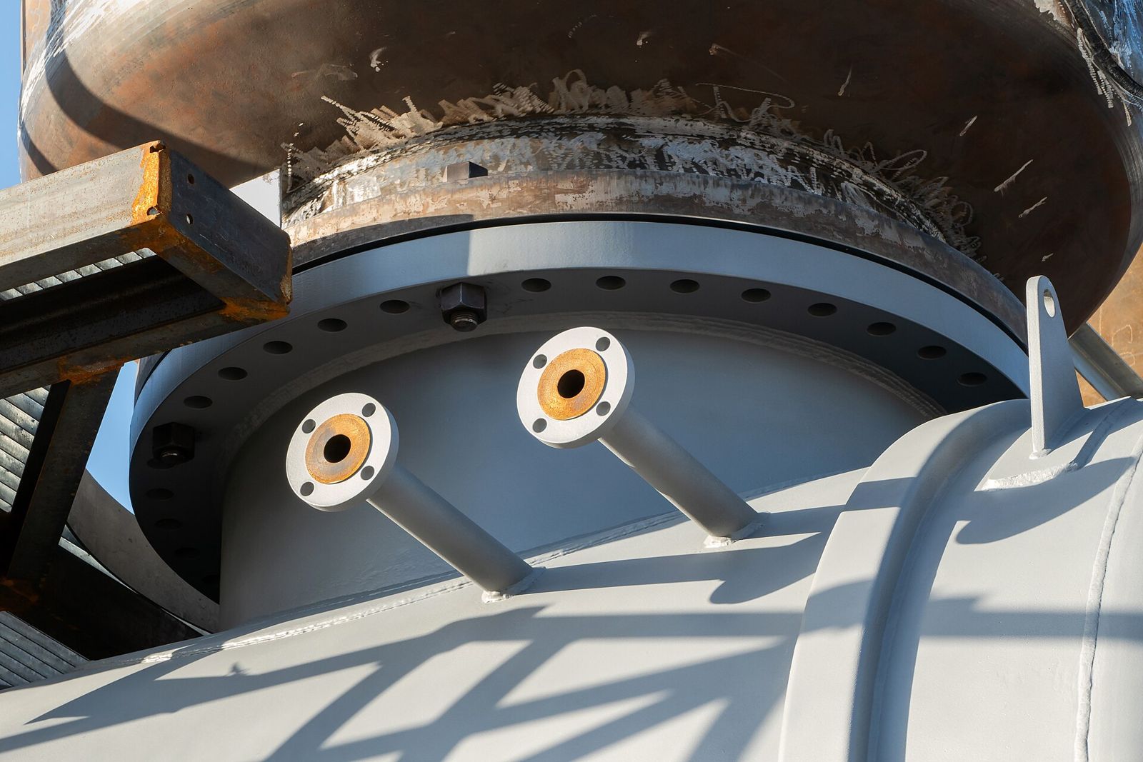
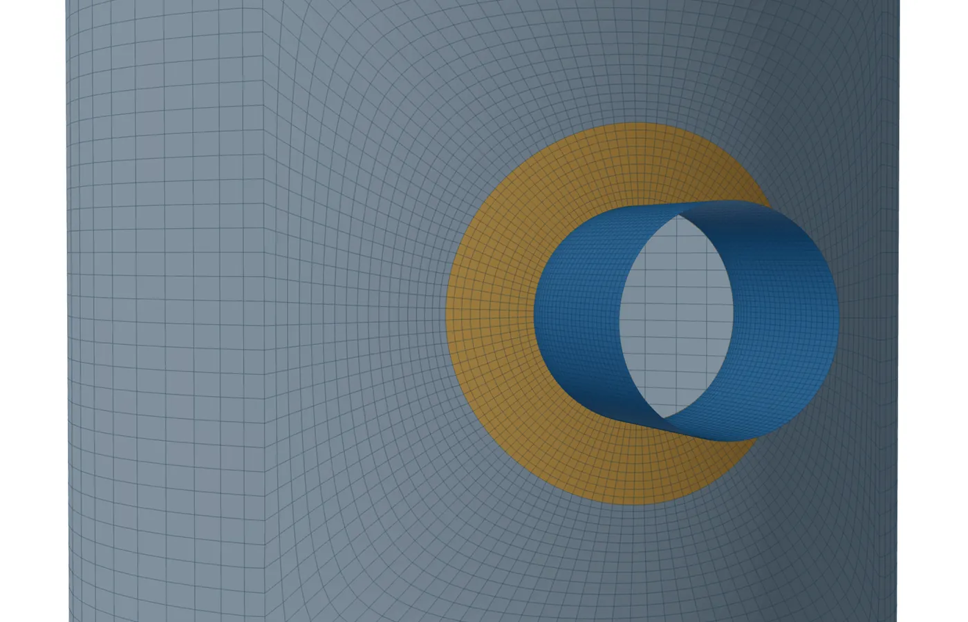
A heavy nozzle is not a plain cylinder: a Q-lip has a lip in the shell opening and a hub that tapers to the nozzle wall, a forging has a wall that changes along its length, and a long weld neck carries one heavy wall out to its weld end. A shell model takes each as a neck whose wall changes along its axis while the bore stays constant. The lip of a Q-lip is meshed as a thicker zone of the shell.
This post covers what each style puts into the model, what is refused, and how the result is read.
Why the neck profile matters
The nozzle wall next to the shell carries the local bending from the nozzle loads and from pressure. A thick neck there is stiffer, takes more of the moment into itself, and spreads the load into the shell over a wider zone. The stress on the nozzle side comes down. On the shell side it moves and changes shape. A model with a plain wall of the nozzle's thickness gets both wrong.
WRC 537 takes the nozzle as a rigid round attachment of its outside diameter, so the neck profile does not enter the shell stress it gives. The shell model is where the profile counts.
The three styles
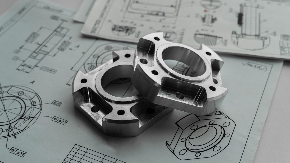
- Q-lip: a lip in the shell opening, given by its outside diameter and thickness; a hub of its own wall and length; then a taper to the nozzle wall, three times the change in wall by default. The lip is meshed as a zone of the shell, like a pad, at the corroded lip thickness, and takes the nozzle's material.
- Forging: a table of points, each a distance from the shell's outside surface and a wall thickness, linear between them. Beyond the last point the wall reaches the nozzle wall by a 3:1 taper, because a square step would distort the shell mesh.
- Long weld neck: the nozzle's own outside diameter and heavy wall, uniform out to the weld end. The weld end is recorded in the report; what lies beyond it is not meshed.
In every style the bore is constant and the wall changes on the outside. Each ring of neck elements takes the wall at its middle, rounded to one of at most 17 levels at least 0.25 mm apart, so the report lists a small number of neck thicknesses rather than one per element.
What is refused, and why
- A neck style on an obround or tombstone opening, or together with a heavy barrel.
- A Q-lip with a pad, a lip not thicker than the corroded shell, a lip inside the hub, or a hub thinner than the nozzle wall.
- A hub and taper, or a forging point, that runs past the nozzle's projection; forging points that do not increase in distance.
- Gussets on a Q-lip or a forged neck.
Each refusal names the input to change. The aim is that a model that runs is a model of the nozzle on the drawing, not of a nearby shape the mesher could manage.
Jobs saved before the neck styles were added open unchanged, as plain necks.
Reading the result
The neck checks read the wall at the section being checked, so a section through the hub uses the hub's wall and a section beyond the taper uses the nozzle's. For fatigue, the outer edge of a Q-lip's lip is read as a butt weld line in the shell, named so in the report.
Set-in against set-on is a different question. A shell model joins mid-surfaces and cannot tell how the nozzle passes through the wall, so that choice belongs to a solid model. The full solid model carries every neck style. The smaller solid detail of the junction refuses a Q-lip or a forged neck and says why; a long weld neck, being uniform, is taken there too.
The solver's tests run each style with pressure and a moment and check that the model balances and that the nozzle-side peak comes out below the plain neck's, as the extra metal says it should.
Where it stops
- 01The bore is constant: a neck that is bored out or stepped on the inside is not offered.
- 02The flange and anything beyond the weld end are not meshed.
- 03Set-in or set-on construction is a solid-model choice; the shell model cannot tell them apart.
- 04Neck styles are new in the shell model, which is early access and under verification.
Try it in FEXLA
The Nozzle loads card's shell model takes Q-lip, forged and long weld neck nozzles, with the wall changing along the neck and the lip as part of the shell.
Open the cardReferences
- ASME Section VIII Division 2, Part 5 (stress checks of the nozzle neck and shell).
- WRC Bulletin 537, which takes the nozzle as rigid.
Method notes this draws on
Next post: Angle and channel clips entered by footprint
Educational article. It explains principles and is not design guidance; follow your governing code and edition.