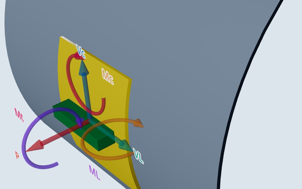
WRC 537 knows only a rigid rectangle on the shell, so an angle or a channel welded to the shell is entered as an equivalent rectangle from Moss, Procedure 7-3. For an angle the half-sizes are 0.2 of its width round the shell and 0.4 of its length along it; for a channel, 0.3 and 0.5. The shell model skips the rectangle and builds the section from its plates, with the direction of each leg as an input.
This post works through both routes and where each stops.
Why an open section is not its outline
A section welded on its edges touches the shell only along its plates. The load goes into the shell where the plates are, and the space between them carries nothing. An angle has two plates meeting at the heel; a channel has a web and two flanges. Neither loads the shell like a solid block of its overall size.
Moss's factors shrink the outline to a rectangle that loads the shell about as the section does. They are smaller for the open sections because less of the outline is metal on the shell. The factors are a rule of thumb from the book's figure, not a derivation.
| Section | C1 = c1·b (round the shell) | C2 = c2·h (along the shell) |
|---|---|---|
| Angle | 0.2·b | 0.4·h |
| Channel | 0.3·b | 0.5·h |
| Single plate, for comparison | 0.5·b | 0.4·h |
Two clips worked through
The angle shows the usual trouble with the method. Its factor round the shell is small, so a long angle soon gives a rectangle narrower than a quarter of its length. The curves are then read at the ratio limit, and the calculator says so. Once the stress ratio of an equivalent-size clip reaches 0.7 the calculator suggests the shell model, because the size itself is approximate.
The placement the factors assume
Moss gives the factors for one placement: width b round the shell and length h along it. A channel or angle turned through 90° has no rule in the book, so the calculator offers none. Enter the two lengths yourself on your own basis, or use the shell model, which takes any rotation.
Torsion on a rectangular clip is recorded but adds no stress in WRC 537. An angle loaded off its heel, or a channel carrying a bracket to one side, can put real torsion into the shell. That is another reason to model it.
The real section in the shell model
- An equal or unequal angle is two legs standing out from the shell, meeting at the heel: an L footprint, as the angle in the calculator's footprint list.
- The direction is an input: which way the leg along the circumference points from the heel, and at which end of the other leg the heel sits. The rotation then turns the whole section.
- A channel is its web and two flanges, meeting at their mid-plane corners.
- The plates share nodes with the shell at their foot, so the load goes in where the metal is.
- Angles and channels mesh on a cylinder, a head, a cone or a flat plate, beside other attachments, and in the clip junction detail and the full solid.
- An angle whose leg is not longer than the other leg is thick is refused.
The channel's footprint on the shell is a U: the web and both flanges stand out from the shell and are welded along their edges. Which way the U opens, round the shell or along it, is set by the rotation. An unequal angle needs one more choice than an equal one: which leg runs round the shell and which along it, since that sets how stiff the clip is for each moment.
Where it stops
- 01The shell at the clip is checked. The clip's own welds and the steel it carries are not.
- 02The equivalent rectangle is Moss's rule of thumb, for his placement only.
- 03WRC 537 takes clips on a cylinder only; heads and cones go to the shell model.
- 04Angle clips are new in the shell model, which is early access and under verification.
Try it in FEXLA
The Nozzle loads card checks angle and channel clips by their Moss footprint in WRC 537, and builds the real section in the shell model.
Open the cardReferences
- D. R. Moss and M. Basic, Pressure Vessel Design Manual, 4th ed., Procedure 7-3 (Fig. 7-10) and Procedure 7-4 note 3.
- WRC Bulletin 537.
Method notes this draws on
Next post: Platform and ladder clips: the loads and what is checked
Educational article. It explains principles and is not design guidance; follow your governing code and edition.