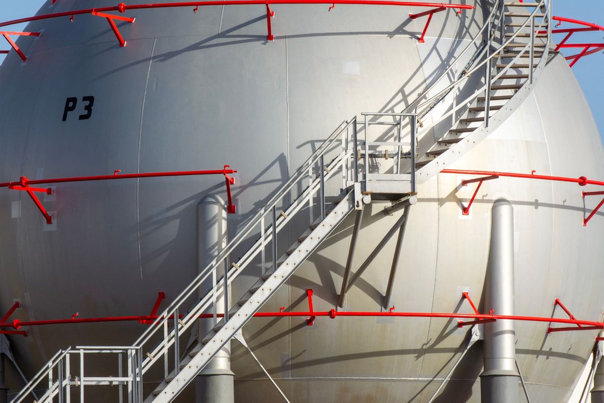
A platform or ladder clip carries the steelwork's reactions into the vessel shell: the weight of the steel and grating, the live load on the platform, and wind on the platform and ladder. The vessel check is of the shell at the clip edge, by WRC 537 on a cylinder or by the shell model elsewhere. The clip plate, its bolts and the platform steel are checked by the steel design that supplies the reactions.
This post covers where the loads come from, how they are moved to the shell surface, and what is checked.
Where the loads come from
The vessel engineer rarely designs the platform. The reactions at each clip come from the platform's design, case by case: dead load of the steel, grating and handrail; the live load the platform is rated for; wind on the platform, the ladder and its cage; for a tall column, seismic as well. Each case gives a force at the bolt or the bearing point of the bracket.
- Dead and live loads are mostly vertical: along the shell axis on a vertical vessel.
- Wind on the platform gives a horizontal force, which reaches the shell as a radial load or a shear round it, depending on the bracket's direction.
- A ladder clip carries the ladder's weight and its share of wind. The loads are smaller, but ladder clips are many and often on thin upper courses.
- The loads are taken at the levels the platform design gives. They are not derived here.

Moving the loads to the shell surface
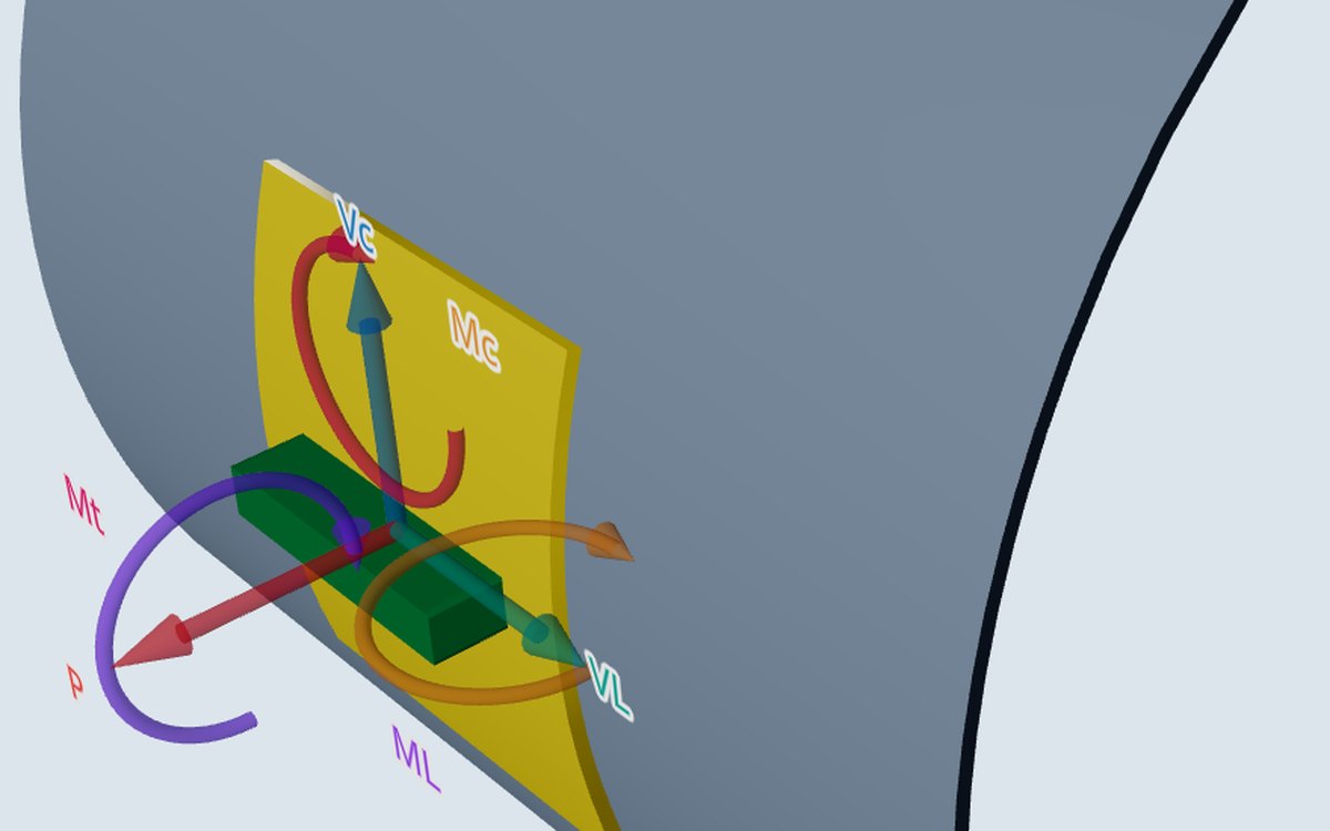
WRC 537 takes six loads at the clip centre on the shell surface. A bracket's reaction acts out at the bolt, some distance from the shell, so each force brings a moment with it: the force times its lever arm to the shell surface.
A reaction that is off the clip's centreline round the shell also gives torsion. On a rectangular clip WRC 537 records the torsion but adds no stress for it, as the bulletin has no accepted method. A large torsion is a reason to use the shell model.
What is checked
- The shell at the clip edge, at the eight points round its edge, each stress against its allowable.
- With a pad, both edges: the clip edge on shell and pad, and the pad edge on the shell alone.
- The shears as stress spread over the clip's sides, VC/(4·T·C1) and VL/(4·T·C2).
- A clip that is a rolled section is entered by its Moss footprint; at a stress ratio of 0.7 the calculator suggests the shell model.
A pad spreads the clip's load over more shell, but its own edge is checked on the shell thickness alone, with only the shell's allowable. A pad that is too small moves the problem from the clip edge to the pad edge rather than removing it. The report shows both edges, so the governing one is plain.
Clips close together act as one attachment. Moss's rule of thumb takes clips nearer than √(R·t) round the shell, or 152 mm along it, as one. A platform bracket with two clips side by side is often that case.
Clips on heads, cones and the top of the vessel
WRC 537 takes clips on a cylinder only. A clip on a head or a cone goes to the shell model. A top platform standing on legs on the top head or cone, or across a top shell-to-cone junction, is its own job on the Vessel on legs card: the platform's dead, live and wind loads at the leg ends, the local stress at the leg welds, the legs' membrane stress and buckling. Legs across a shell-to-head junction at the top are refused.
On tall columns, wind can set the column vibrating, and platform clips then see many load cycles. That is a fatigue question for the clip welds, which a static clip check does not answer.
Where it stops
- 01The platform reactions are yours to give; they are not derived from the steel layout.
- 02The clip plate, its bolts and welds, and the platform steel are not checked.
- 03Fatigue of the clip welds under wind-induced vibration is not part of the clip check.
- 04The shell model for clips on heads and cones is early access and under verification.
Try it in FEXLA
The Nozzle loads card checks platform, ladder and support clips on a cylinder by WRC 537, with the shell model for clips on heads and cones.
Open the cardReferences
- WRC Bulletin 537.
- D. R. Moss and M. Basic, Pressure Vessel Design Manual, 4th ed., Procedure 7-3.
Method notes this draws on
Next post: Trunnions against plate lugs: what each check covers
Educational article. It explains principles and is not design guidance; follow your governing code and edition.