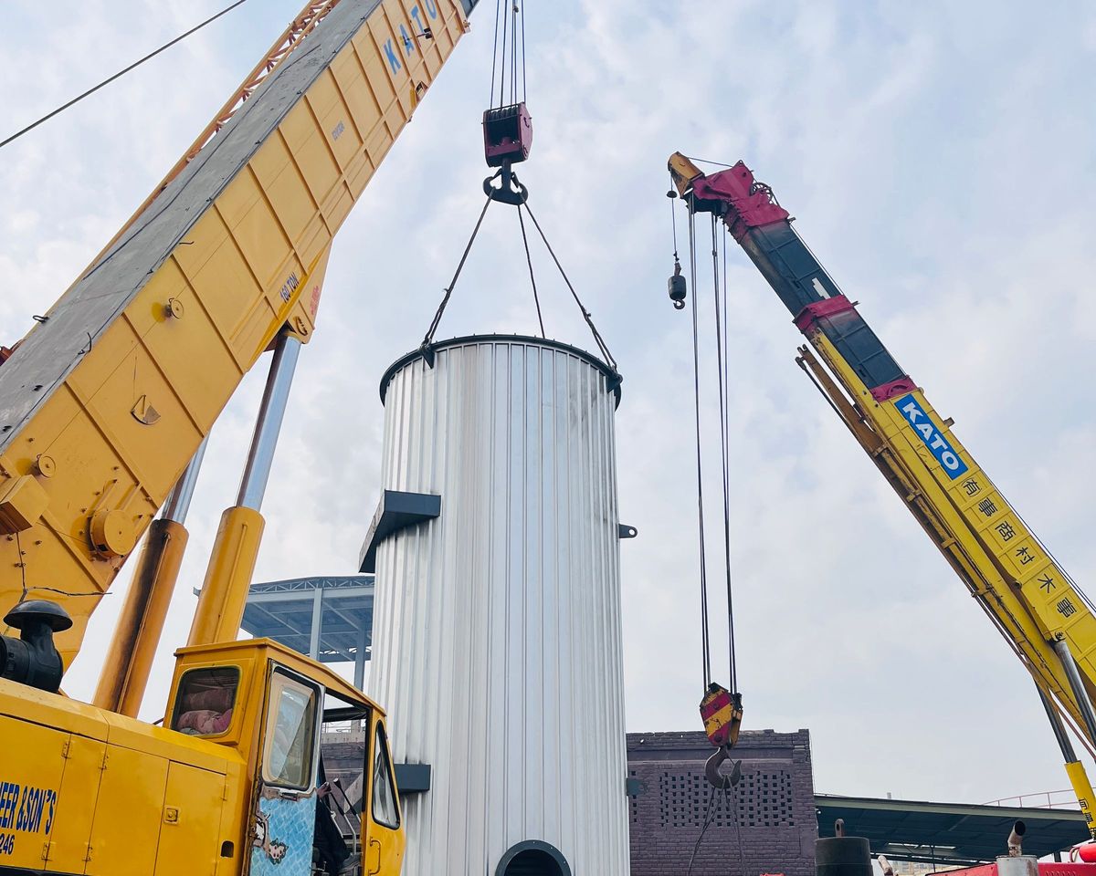
A plate lug takes the lift load through a pin in a hole, so its checks are at the hole: net section, shear above the hole, bearing, then the base and its welds. A trunnion is a round tube welded to the shell with the sling hung on it, so it is checked as a short beam: bending at the shell, shear, the pull along it and the ring weld at its root. Both are checked on the factored lift load, and both pass their load into the shell as a local load that needs its own check.
This post sets the two side by side.
The plate lug: checks at the hole and the base
The lug load is resolved into the plate's axes: along its base, normal to it, and across the plate, the side load being at least 10 % of the lug load by Moss. The hole checks take the full resultant. The base checks take the components one by one.
- Net section at the hole: P / ((A − D1)·t) ≤ 0.45·F_y, with cheek plates adding to t.
- Shear above the hole: P / ((R − D1/2)·t) ≤ 0.4·F_y.
- Bearing on the pin: P / (D2·t) ≤ 0.9·F_y.
- Base: axial load and the two bendings in one interaction, and base shear at 0.4·F_y.
- Base fillet welds from the line force, at 108.9 MPa for E70XX on the throat (Moss 10-3).
The trunnion: a short beam with a ring weld
A trunnion has no hole. The sling bears on the tube a distance e out from the shell. The load square to the trunnion, V, is the lift load across and along the vessel axis; the sling spread pulls along it as F_a. The checks follow Moss 10-8, Type 3.
The root weld is checked as a ring round the tube, from the moment, the pull and the shear together, with a minimum throat of 9.5 mm (3/8 in).
How each loads the shell
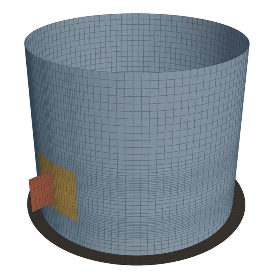
The two load the shell differently. A plate lug stands on a rectangle of shell, long in the plane of the plate, and is checked in WRC 537 as a rectangular clip of that footprint, with or without its pad. A trunnion is a round attachment, checked as a round one: the lift's load across the vessel goes round the shell, the load along the axis is longitudinal, and the pull along the trunnion is radial.
A trunnion's lever e also puts a moment into the shell: V·e at the root. A plate lug's load acts at the pin, so its components along the base and across the plate bend the base over the pin height. In both cases the moment, not the force, usually sets the local stress in the shell.
What each check leaves out
- Plate lug: the shackle is checked for fit, not rated; its rating is the maker's.
- Trunnion: there is no check of a sleeve, a retaining plate or the sling end; only the tube and its root weld.
- Both: the hand checks know nothing of the shell's local stress. That is the WRC 537 check and the shell model.
Two tailing lugs set either side of the lift plane are offered for plate lugs pointing up or down only, not for a trunnion or a lug to the side. Each takes half the tail load, resolved into its own plane. In the shell model a trunnion can have a round pad under it, as a nozzle can.
Where it stops
- 01Plain plate lugs and trunnions only; flange lugs and side lugs are not offered.
- 02The checks are allowable-stress hand checks on the factored lift load; the lift itself is taken as quasi-static.
- 03There is no sleeve, pin or retaining-plate check for a trunnion.
- 04The shell model of a lug or trunnion is early access and under verification.
Try it in FEXLA
The Lifting and tailing lugs card checks plate lugs and trunnions by Moss and AISC, the shell under each by WRC 537, and builds the shell model.
Open the cardReferences
- D. R. Moss and M. Basic, Pressure Vessel Design Manual, 4th ed.: 10-3 (welds), 10-4 (lift loads), 10-8 (trunnions).
- AISC allowable stress design, as used in Moss.
Method notes this draws on
Next post: A tailing lug with a base ring, a compression ring or a strut
Educational article. It explains principles and is not design guidance; follow your governing code and edition.