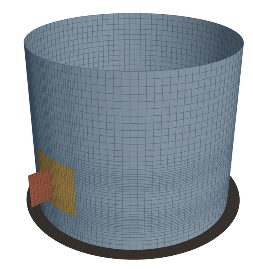
A tailing lug near the skirt base pulls the skirt's base ring sideways while the vessel is upended, and the ring bends in its own plane. Moss 10-5 checks that ring by hand, as a ring under a point load, with struts across the skirt as the way to stiffen it. The shell model can mesh the ring itself, with the lug on the skirt, standing on the ring, between the base ring and a top compression ring, or continued by a strut across the skirt.
This post covers the hand check, the struts and the arrangements the model builds.
The base ring as a ring under a point load
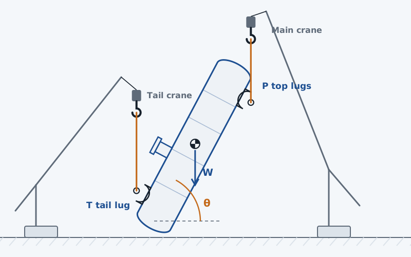
During the lift the base ring is not bolted down. The tail load T acts at the lug, radially on the ring, and the skirt reacts it by shear round the circumference. Moss's one-point case gives the ring's moment and hoop force at an angle α from the load as coefficients of T. The tool uses them in closed form.
The moment is evaluated every half degree from 0 to 180° and enveloped, since the loads reverse when the vessel is set down. The checks are the bending |M|·c/I at 0.66·F_y and the interaction of hoop force and bending.
Struts across the skirt
Moss 10-5 stiffens the ring with struts that tie points of the ring together. Two points is one strut across the diameter from the lug. Three points is a triangle. Four points is the diameter with a diamond. Each strut carries a fixed fraction of T, and the ring moment drops because the ring now spans between strut points instead of the whole half-circle.
Each strut is checked both ways, since the loads reverse on setting down: in tension at 0.6·F_y on its area, and in compression against the AISC column allowable for its KL/r. A long strut across a large skirt can be decided by compression, where its radius of gyration matters as much as its area.
The arrangements the shell model meshes
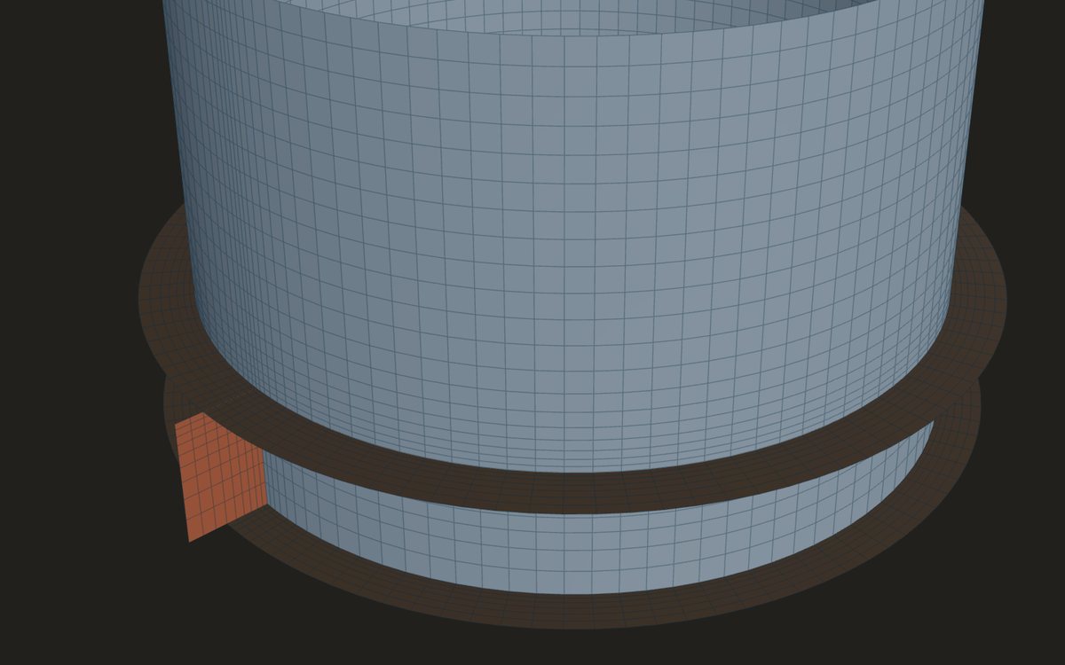
- With the ring meshed, the skirt is modelled base up: the base ring is a plate at the free base edge, the skirt is held at its head joint, and the lug stands at its real height above the base.
- A top compression ring, outside the skirt, can be added above the lug.
- The lug can stand on the base ring, its plate's bottom edge welded to the ring. There is no pad under a lug on the ring in this version.
- The lug plate can act as a gusset between the base ring and a compression ring sitting on its top edge; both rings share the plate's nodes.
- A strut, an I or a channel, can continue the lug plate through the skirt to the far side, welded there. Its flange ends are not welded in the model.
The hand check of the ring stays beside the model, with all of T at the lug. For a ring stiffened by struts, the one-point result is an upper bound.
Moss 10-5 also gives a different tail attachment: a beam across the base under the skirt, the tail pin beyond the skirt. It is checked by hand in bending, in its bolts for shear and tension, in the fillet weld to the skirt, and for crippling of the skirt over a spread length. The panel's default beam fails some of those checks, which shows they respond; it is not a recommendation.
Where it stops
- 01The hand check puts the whole tail load at the lug, for twin lugs as well; no share per lug is taken in the ring.
- 02Anchor chairs, gussets round the anchor bolts and the foundation are not checked.
- 03The struts in the shell model are a continuation of the lug plate; Moss's strut patterns are hand checks.
- 04The shell model of the lug and ring is early access and under verification.
Try it in FEXLA
The Lifting and tailing lugs card checks the base ring and its struts by Moss 10-5, and meshes the ring, a compression ring or a strut with the lug.
Open the cardReferences
- D. R. Moss and M. Basic, Pressure Vessel Design Manual, 4th ed.: 10-4 (lift loads), 10-5 (base ring and stiffeners, Table 10-7).
- AISC allowable stress design: column allowable as Moss prints it.
Method notes this draws on
Next post: Lifting a vertical vessel: the Moss lift steps
Educational article. It explains principles and is not design guidance; follow your governing code and edition.