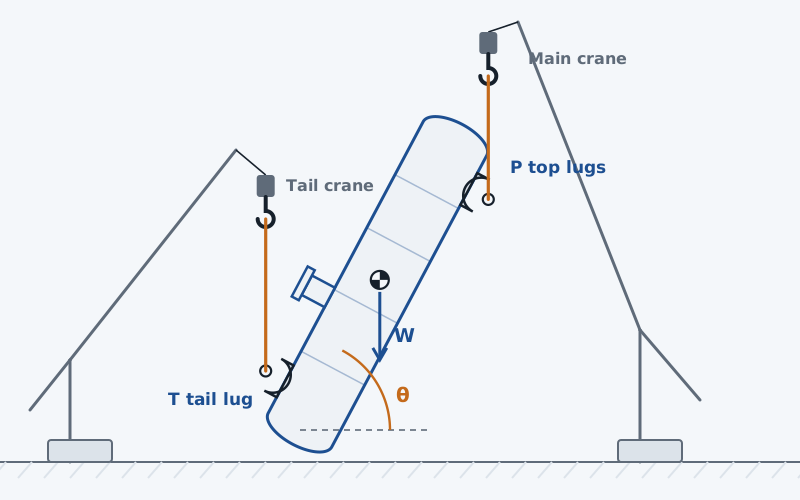
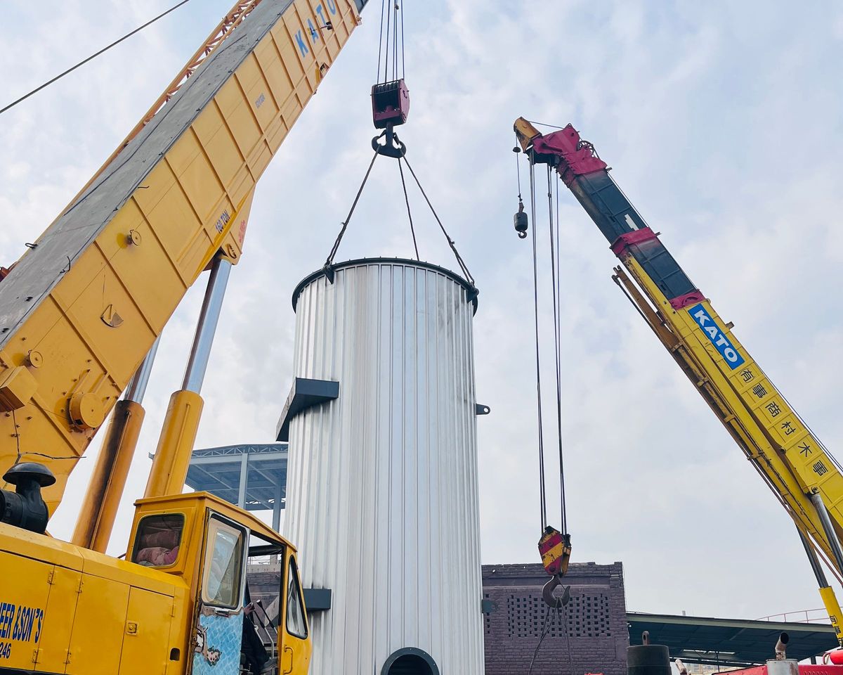
An upending lift is worked as statics at a list of angles: the vessel is turned about the tail pin from horizontal to vertical, both hook lines stay vertical, and at each angle the moments about the tail pin give the pick load. The tail takes the rest. The largest lug load over the list then goes to the lug, weld and shell checks.
This post walks through the steps with the default lift of the tool, and the cases the steps flag.
Placing the points
Three points matter: the centre of gravity G, the tail pin T and the pick point L. Each is given by its position z along the vessel from the base and its offset e in the lift plane, positive upward while the vessel lies flat. A tail lug standing out from the skirt has a negative offset. Turning the vessel by θ gives each point a horizontal position X.
With the pick point and the centre of gravity on the axis this is Moss 10-4. Working in X needs no extra formula when they are off the axis, which is why the tool uses it.
The steps of the default lift
The default angle list is 0, 15, 30, 45, 60, 75 and 90°. The default vessel has its centre of gravity 6000 mm up, the tail pin at 300 mm with an offset of −1400 mm, and the pick point at 14000 mm on the axis.
| Angle | Pick load P | Tail load T |
|---|---|---|
| 0° | 166.4 kN | 233.6 kN |
| 30° | 151.8 kN | 248.2 kN |
| 45° | 139.8 kN | 260.2 kN |
| 60° | 116.2 kN | 283.8 kN |
| 75° | 22.4 kN | 377.6 kN |
The statics run twice: on the erection weight W_E for the shackle, and on W_L = K_L·W_E for the lug, welds and shell. Moss gives K_L as 1.5 to 2.0. Below 1.5 the tool warns, and below 1.8 it warns that the checks do not reach the F_y/3 basis of ASME B30.20.
The angles that need a warning
- The centre of gravity passes the pick point: the tail goes slack, the tail load is set to zero and the vessel is shown hanging from the pick lugs.
- The centre of gravity falls behind the tail pin: the pick load goes negative and the arrangement cannot hold the vessel. In the default lift this happens above 76.2°, where tan θ = 5700/1400.
- The pick point straight above the tail pin: the split cannot be found and the step is skipped.
The 76.2° case is the one that matters in practice. A tail lug far out from the axis puts the tail pin ahead of the centre of gravity before the vessel is upright. Either the angle list stops before it, or the tail pin offset is revisited.
With two tailing lugs set at ±β about the lift plane, the tail pin is no longer at the lug's full projection from the axis but at that distance times cos β. The tail offset in the statics should be set to that value, or the steps place the tail pin too far out.
From the end loads to each lug
- Each end's load is shared by its lugs. Along the vessel axis a lug sees f·sin θ, across it f·cos θ.
- Sling spread at the top adds a radial load f·tan β, with β the sling angle from vertical.
- A side allowance of at least 10 % acts out of the lift plane, and the lug resultant is √(f² + lateral²).
Shell bending at the first pick
The vessel bends most as a beam at 0°, lying between its two hooks. The tool takes the moment from the factored weight at the centre of gravity, and separately from the weight spread along the length, and gives the thin-ring stress σ_b = 4·M/(π·D_m²·t). For the default lift on a 2420 mm mean diameter, 20 mm shell, that is 26.1 MPa on W_L = 720 kN.
Where it stops
- 01The vessel is rigid and the lift quasi-static: no dynamic effect beyond K_L, no wind, no crane or boom geometry.
- 02The governing step is the largest among the listed angles, not an interpolated maximum.
- 03Crane selection and the lift plan are not checked.
- 04The shell model of each lug is early access and under verification.
Try it in FEXLA
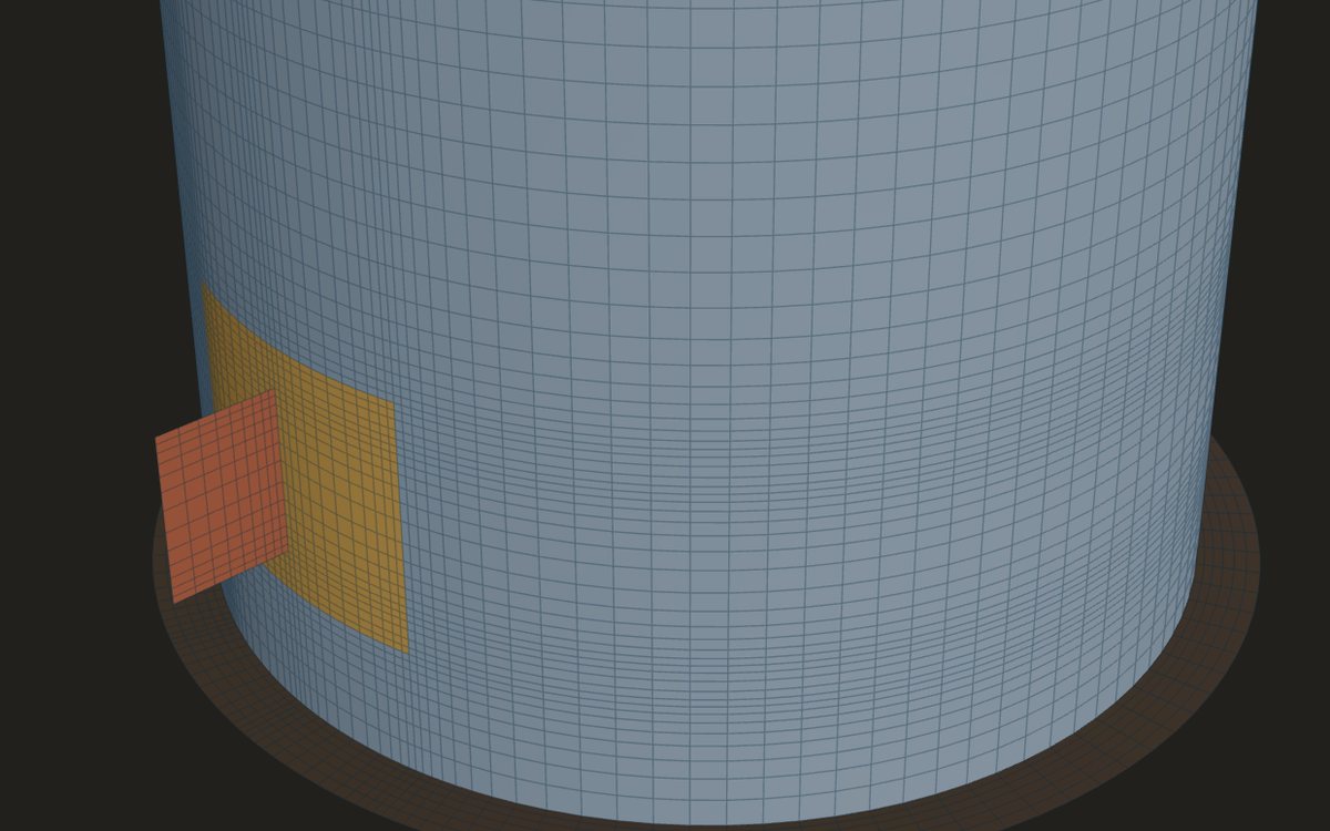
The Lifting and tailing lugs card runs the lift statics at your angle list and takes the worst lug load to the lug, weld, shackle and shell checks.
Open the cardReferences
- D. R. Moss and M. Basic, Pressure Vessel Design Manual, 4th ed., 10-4 (lift loads).
- ASME B30.20 (below-the-hook lifting devices), for the F_y/3 basis.
Method notes this draws on
Next post: Shackle selection and the pin-hole fit on a lifting lug
Educational article. It explains principles and is not design guidance; follow your governing code and edition.