A local stress model is checked in the corroded condition: every wetted or exposed face loses its allowance before the mesh is built. The shell model takes an inside and an outside allowance on the shell, head or cone, both on the nozzle wall, one on the outer face of a pad, and one on each face of a clip or lug plate. It can also run the same checks on the new, uncorroded vessel and report the worse of the two.
This post goes through where each allowance is taken, what it does to the geometry, and why the new condition is worth a second run.
The shell: two allowances move the mid-surface
A shell element sits on the mid-surface of the wall, so the allowance changes two things at once: the thickness and where the wall is. The corroded thickness is the nominal one less the inside and the outside allowance. The inside diameter grows by the inside allowance, so the mid-surface sits at the inside radius, plus the inside allowance, plus half the corroded thickness. A thickness with nothing left is refused.
The decay length sets the mesh near the attachment and the size of the zone where local stress is read, so both follow the corroded wall. A thinner wall also raises the bending part of the local stress more than the membrane part, because bending stress goes with the square of the thickness.
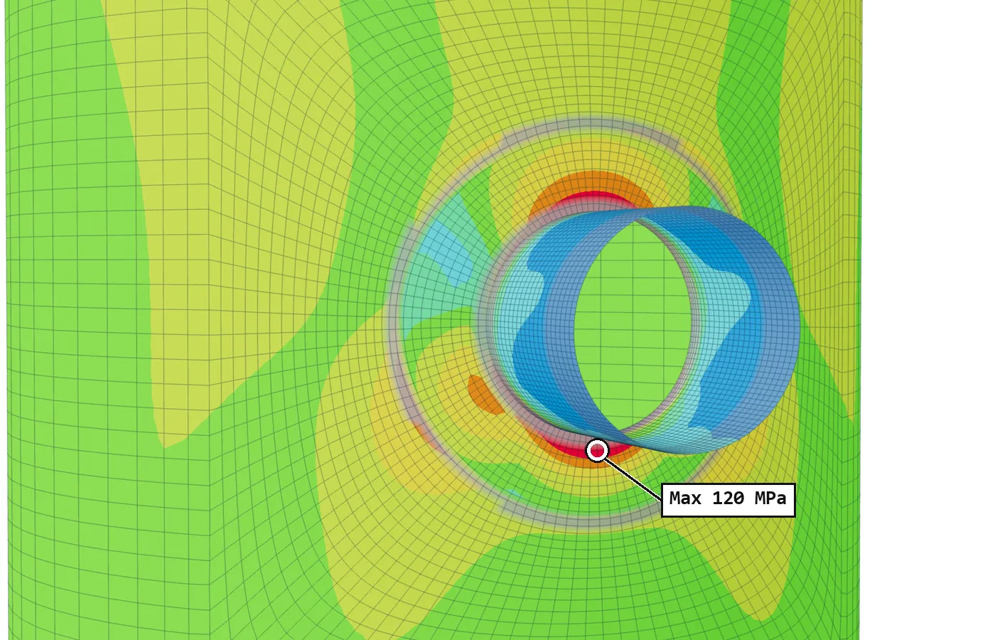
The nozzle: wall thinner, bore kept, ends in place
A nozzle takes its own inside and outside allowance. Its wall loses both and its bore stays at the drawn size. The same holds for a heavy barrel or a variable neck. An inside projection keeps the inside allowance only.
Lengths along the nozzle are measured from the uncorroded outside surface of the vessel: the projection, the barrel, the neck points and the gusset height. So the loaded end of the nozzle does not move when the shell corrodes. The nozzle loads from the load table act where the drawing puts the flange face, in both conditions.
Pads, clips and lug plates
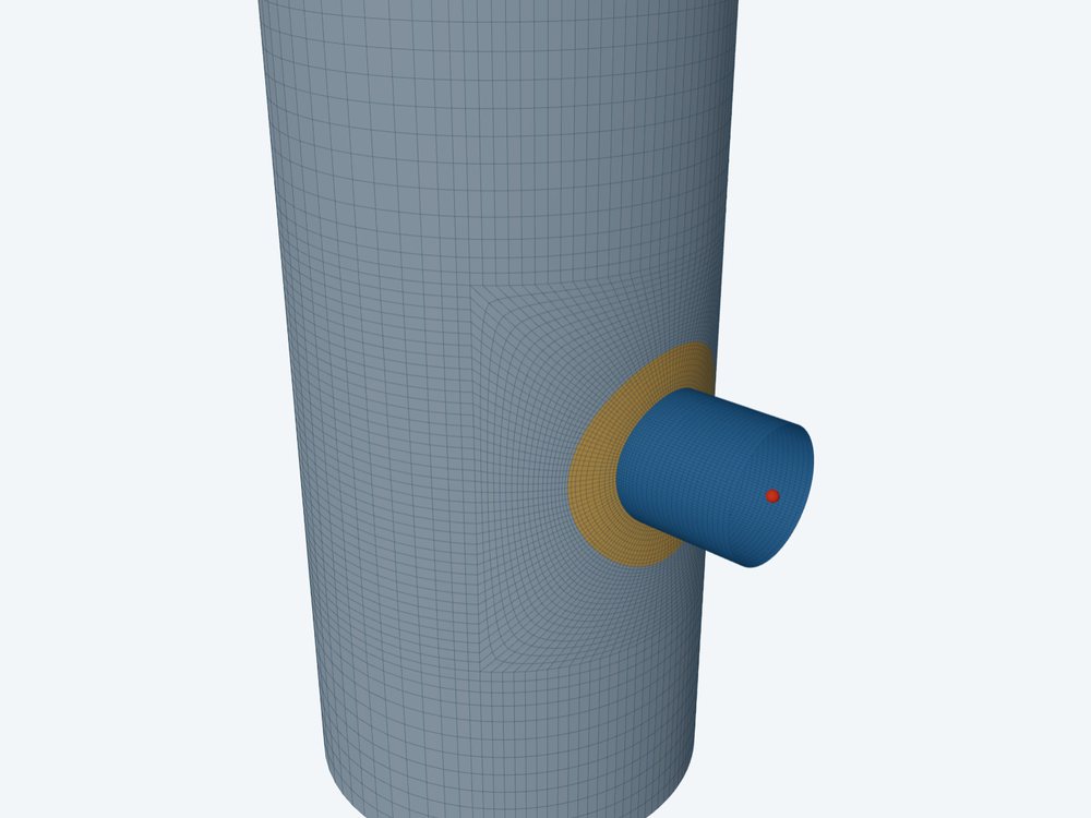
- A reinforcing pad or a clip pad loses its allowance off its outer face, the face exposed to the weather.
- A clip, lug or leg plate loses its allowance off each face. Each plate is then twice the allowance thinner. This is the conservative reading, chosen because both faces of a standing plate are exposed.
- The shell under a pad keeps its own outside allowance as well. The pad is welded over it, but the model does not credit that face as protected.
- Fillet welds are not in the shell geometry. Their sizes are taken as entered.
A clip plate 12 mm thick with a 1 mm allowance is checked at 10 mm. On a slender bracket that can move the stress more than the shell's own allowance does, because the plate's bending stiffness goes with the cube of its thickness and sets how much moment the plate passes into the shell.
Why the new condition is run as well
Corroded is usually the worse case for stress, but not always. A thicker, stiffer new wall draws more of a displacement-controlled load, such as thermal growth of the attached line, so secondary stress can be higher new than corroded. The hydrostatic test is normally made on the new vessel. And a fatigue check on the new wall sees different weld-toe stresses.
With the new condition ticked, the elastic checks run a second time on the same model with every allowance set to zero: inside and outside, nozzle, pad and member. The worse condition decides the verdict, and the results line and the report table show both. Plots, solid details, limit load and buckling stay on the corroded model.
In the WRC 537 calculator
The WRC 537 calculator takes one allowance. The shell is checked at its thickness less the allowance and a pad at its thickness less the same allowance. There is no outside allowance and no second run. When the two tools are compared on one nozzle, check that the same allowances went into both.
Where it stops
- 01Uniform corrosion only. Local thinning, pitting and grooving at a weld are not modelled.
- 02The new condition reruns the elastic checks; limit load, buckling and solid details stay corroded.
- 03Weld sizes are taken as entered, with no allowance taken off them.
- 04The outside, pad and member allowances are new in the shell model, which is early access and under verification.
Try it in FEXLA
The Nozzle loads card builds the shell model with inside, outside, pad and plate allowances, and can check the new vessel beside the corroded one.
Open the cardReferences
- ASME Section VIII Division 2, Part 5 (analysis in the corroded condition).
- WRC Bulletin 537, for the shell and pad thicknesses in the bulletin check.
Method notes this draws on
Next post: Shell courses and thickness steps with UW-9(c) tapers
Educational article. It explains principles and is not design guidance; follow your governing code and edition.