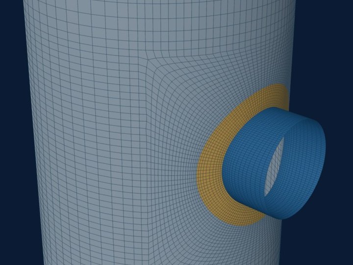
A vessel shell is rarely one thickness: courses step down a tall column, and the shell below a head is often thinner than the head. Where two plates of different thickness meet, ASME VIII-1 UW-9(c) asks for a 3:1 taper once the difference passes a trigger, and below it the step stays square. Both bend the shell at the seam, and that bending adds to the local stress of any attachment close by.
This post covers how the shell model takes courses, tapers and small steps, and where they matter.
The rule in UW-9(c)
When sections joined by a butt weld differ in thickness by more than a quarter of the thinner one, or 3 mm (1/8 in), whichever is less, the thicker one is tapered at least three times the offset between the surfaces. The rule also covers a thickness reduction within a course. Below the trigger no taper is needed.
Why a seam bends the shell
Under pressure the thin course grows more than the thick one, and the two are held together at the seam. That mismatch gives a discontinuity moment and shear at the joint, as at a head-to-shell junction. If the mid-surfaces do not line up, the axial membrane force N also acts with an offset e, and adds a moment N·e.
On a 2000 mm diameter shell at 1 MPa, the axial membrane force is P·R/2 = 500 N per mm of circumference. A 1 mm offset between mid-surfaces, the case of a 12 to 10 mm step flush on the inside, gives N·e = 500 N·mm per mm. That moment dies away over a few decay lengths √(R·t). Far from any attachment it is small. Inside an attachment's zone it adds to the local membrane plus bending stress.
How the shell model takes courses
- Courses are entered from the bottom seam up, each with its thickness. The alignment is inside flush (the default), outside flush or centred.
- One node surface is used: the mid-surface of the course that holds the first attachment. Every other plate carries a section offset from it, so the real eccentricity is in the model.
- Past the UW-9(c) trigger the thicker plate gets a 3:1 taper beside the seam, built as two to eight rows of elements of stepped thickness and offset.
- Below the trigger the step is square. Its offset is modelled within 2.5·√(R·t) of an attachment's footprint and ignored elsewhere, with a note in the report.
- Every seam and taper edge is a grid line. A nozzle's refined block stops at the nearest seam beyond its footprint, and a seam on a footprint is refused with the clearance needed.
- The shell below a head can take its own thickness instead of the head's.
The stepped cylinder was checked against the hand discontinuity solution for two courses under pressure: the radial growth within 1 % of the free-growth jump, and the peak axial moment within 3 % at the default mesh size and closer on a finer mesh.
The report lists the courses, each seam with its UW-9(c) reading, taper or plain step, and the note on any step whose offset was left out far from the attachment.
When the seam is near an attachment
The seam and the attachment each disturb a zone a few decay lengths wide. When the zones overlap, the two bendings add, and the report reads them together. The seam rows also appear as their own weld lines, so a stress at the taper or the step is reported where it occurs, not smeared into the attachment's zone.
WRC 537 takes one shell thickness and treats the attachment as alone on the shell. A seam within the attachment's decay zone is outside its assumptions, and the shell model is the way to see it.
Where it stops
- 01Fabrication misalignment within the code's tolerances is not modelled; only the design offset is.
- 02A seam that crosses an attachment's footprint is refused, not modelled.
- 03Weld reinforcement and the weld's own shape are not in the shell model.
- 04Courses and tapers are new in the shell model, which is early access and under verification.
Try it in FEXLA
The Nozzle loads card's shell model takes shell courses, tapers and the shell below a head, and reads the seams beside the attachment.
Open the cardReferences
- ASME Section VIII Division 1, UW-9(c) (tapered transitions).
- WRC Bulletin 537, for the single-thickness shell it assumes.
Method notes this draws on
Next post: Insert plates round a nozzle: how a local model takes them
Educational article. It explains principles and is not design guidance; follow your governing code and edition.