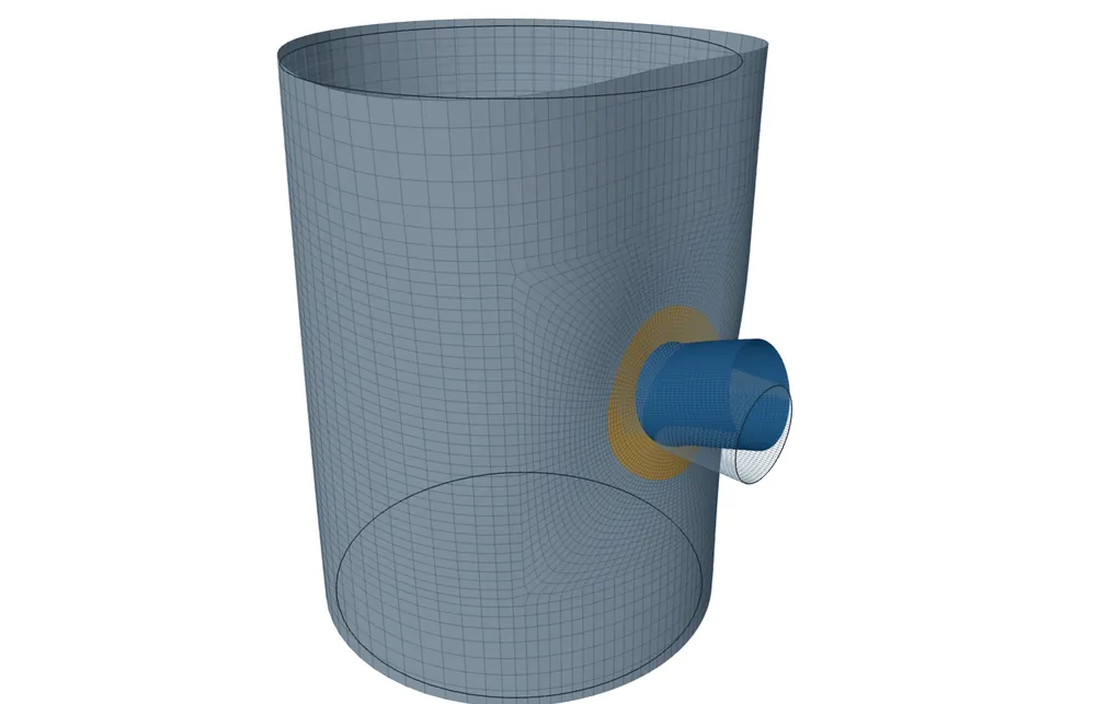
Long enough for the shell to go oval as it does in the real vessel: out to the real heads, rings or cone junctions, or 50√(R·t) each side of the nozzle when they are not known. A model cut short and held round at its cut is too stiff, so it reads the stresses from a radial force and a circumferential moment low and those from a longitudinal moment high.
Pressure alone hardly cares. This post explains why with a drinks can, shows the numbers from our solver and from CalculiX, and says what the tool now asks for.
The drinks can
Take an empty drinks can and press your thumb on its side. The can does not only dent under your thumb. The whole section squashes into an oval, and the oval spreads a long way along the can.
Now slide two tight rings onto the can, one close to each side of your thumb, and press again. The can feels much stiffer, because the oval cannot spread past the rings.
A shell model of a nozzle is a piece of the vessel cut out around it. The model has to be held somewhere, and where it is held, at a cut end, it holds the shell round. A cut close to the nozzle is a ring pushed up to the thumb.
Why the short model reads wrong
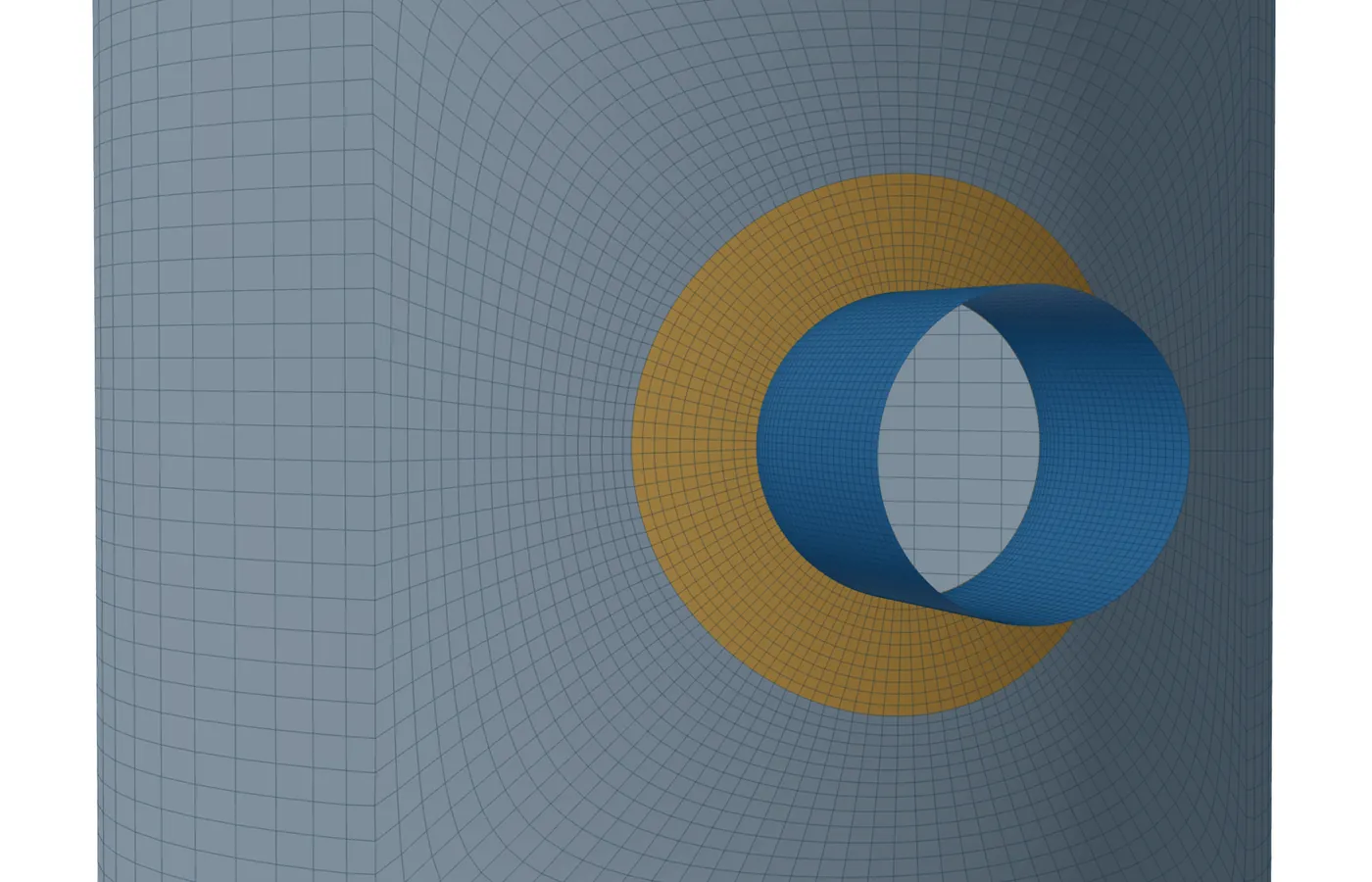
A nozzle load reaches along the shell in two ways. Bending of the wall right at the weld dies out within about 2.5√(R·t), and that is what short models were sized for. A push on the nozzle or a sideways bend also turns the shell into an oval, and the oval travels much further, roughly R·√(R/t).
Held round too close, the shell cannot oval freely, so it carries a radial force P and a circumferential moment MC with less bending than it really does. Those stresses read low, on the unsafe side. The longitudinal moment ML loads the shell more locally, and the short model reads it a little high, on the safe side.
Short against long, in two programs
We took the three nozzles where the effect was largest and modelled each one twice: short, by the former rule of about 5 to 7√(R·t) each side, and long, 50√(R·t) each side, with 10 kN or 10 kN·m on the nozzle. The same meshes with the same holds at the cut ends were then solved in CalculiX, a second, independent program.
| Load | Vessel D/t, nozzle d/D | Short, MPa | Long, MPa | Change, FEXLA | Change, CalculiX |
|---|---|---|---|---|---|
| P | 100, 0.5 | 4.3 | 8.1 | −47 % | −47 % |
| P | 100, 0.3 | 7.3 | 12.3 | −41 % | −41 % |
| P | 50, 0.5 | 1.4 | 2.3 | −38 % | −38 % |
| MC | 100, 0.5 | 18.4 | 24.0 | −23 % | −23 % |
| MC | 100, 0.3 | 44.2 | 48.8 | −9 % | −9 % |
| MC | 50, 0.5 | 5.6 | 6.6 | −16 % | −16 % |
| ML | 100, 0.5 | 7.0 | 6.5 | +8 % | +8 % |
| ML | 100, 0.3 | 18.3 | 17.8 | +3 % | +3 % |
| ML | 50, 0.5 | 2.4 | 2.2 | +6 % | +6 % |
Both programs show the same change in the same direction, and on the same model they gave the same stress to within 0.6 %. So the effect is not a quirk of one solver. It comes from where the model holds the shell round.
When it matters, and when it does not
- It matters most for large nozzles, d/D of about 0.3 and above.
- It matters more on thinner shells: the higher the D/t, the further the oval reaches.
- It matters for the nozzle loads P, MC and ML, the radial force most of all.
- It hardly matters for a small nozzle, which makes only a small oval.
- It hardly matters for pressure alone: the change stayed under about 3 % in our study.
What holds a shell round
In a real vessel the shell is held round by something stiff all the way round it: the heads, stiffening rings, tray-support rings and cone junctions. These are its lines of support. A few lugs, legs or clips do not count. They touch the shell at a few points and do not stop it going oval.
Other attachments nearby matter in three ways. A small nozzle or clip close by has little effect on the oval and can be left out. A large nozzle or a pad close by stiffens the shell: model it with the first one. A ring or a head close by is a line of support: model the shell out to it.
Vertical and horizontal vessels, and heads
On a vertical column the heads, tray-support rings and stiffening rings are usually close together, so the real lines of support are often nearer than 50√(R·t). Model to them. The bending of the whole column under wind or earthquake is a separate, global check. The local model takes the nozzle's own loads and the pressure.
A horizontal drum is the opposite. Its heads are far apart and it seldom has rings between them, so the oval can run a long way: use the real tangent-to-tangent length. The weight of the liquid also ovals the shell near the supports, and saddle supports are outside the scope of this tool.
A nozzle on a head needs some cylinder below the head in the model. Take at least 2.5√(R·t) of attached shell so the junction bending is complete, and more for a large nozzle or one near the knuckle. The tool models 4√(R·t) below the head unless you enter another length.
What the tool does now
- It asks for the real vessel along the axis: the tangent-to-tangent length and the nozzle's place on it, or the distance to the nearest head, ring or cone junction each side. The model runs out to those lines and holds the shell round there.
- When they are not given, it uses a long model: each cut the largest of 50√(R·t), one nozzle diameter and one shell radius beyond the nozzle.
- On a thin shell, where R·√(R/t) is longer still, it says so plainly and asks for the real vessel.
- When a typed length cuts the shell closer than 50√(R·t), it warns that the radial-force and circumferential-moment stresses may read low, unless that end really is a head or a ring.
- Far from the nozzle the elements grow longer along the axis, so a long model costs fewer of them.
These changes are in the workbench release now being prepared. Shell model results are early access and under verification.
Where it stops
- 01The check covered three radial nozzles without pads on one shell size, each load alone. Pads, offset nozzles and groups were not measured.
- 02Above a D/t of about 100 no fixed length is right: only the real distance to the heads or rings settles the answer.
- 03Saddle supports and the global bending of the vessel are outside this local model.
- 04Shell model results are early access and under verification. Until that is finished they are not a source of design values.
Try it in FEXLA
The Nozzles and clips card runs WRC 537 and builds the shell model of the same nozzle; give it the real vessel and it models the shell out to the heads and rings.
Open the cardReferences
- ASME Section VIII Division 2, Part 5, Design by Analysis: the PL+Pb+Q value read at the junction.
- Thin-shell theory: the decay length √(R·t) used throughout the method notes.
Method notes this draws on
Next post: Corrosion allowance in a local model: inside, outside, pads and clips
Educational article. It explains principles and is not design guidance; follow your governing code and edition.