Being added. The real-vessel input, the round end at a line of support and the graded far rows are on the FEA workbench release branch (ajay/release-2026-11-01), not merged to its main branch when this note was written. The 50√(Rm·t) automatic length came in on ajay/model-length-end-stiffness and is part of the same release.
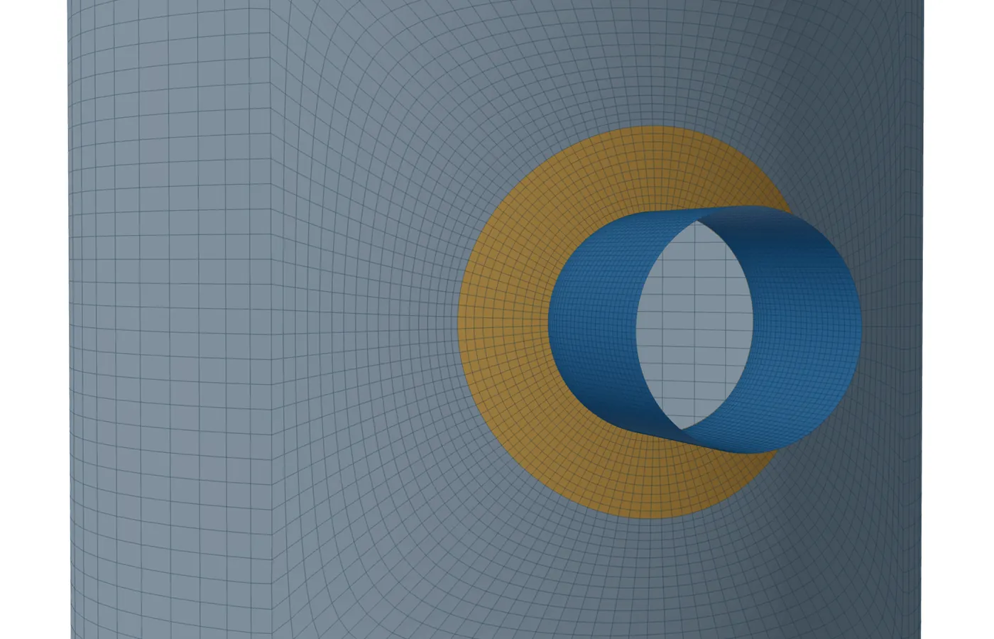
A shell model of a nozzle is a piece of the vessel cut out around it. The bottom cut is the support: every node is held along the meridian, round the circumference and against meridional rotation, free to move normal to the shell, so the shell is held round there. The top cut is free and closed: it carries the end thrust and may oval. Wherever the model holds the shell round and the real vessel does not, the model is too stiff.
Two lengths in a cylinder
Local bending at the junction dies out within about 2.5√(Rm·t). A radial force P or a circumferential moment MC also ovals the whole cross-section, and the oval fades only over about Rm·√(Rm/t). In √(Rm·t) units that length is Rm/t: 25 at D/t 50, 50 at D/t 100, 250 at D/t 500. Pressure barely ovals the section, so it hardly cares about the length.
The rule as coded
- Real vessel given (tangent-to-tangent length and the attachment's place on it, or the distance to the nearest head, stiffening ring or cone junction each side): each end of the model runs to its line of support, held round there, but never further than the automatic length. An end whose line lies past the automatic length is cut at that length instead.
- Not given, Automatic: each cut end lies beyond the outermost attachment by the largest of 50√(Rm·t), one attachment diameter and one shell radius. The note says that the real vessel would give a shorter, more accurate model.
- Thin shell: when Rm·√(Rm/t) is more than 5 % past that cut, the note adds the ovalisation length and asks for the real vessel, because the heads or rings then decide the answer.
- As entered: the length and position typed are used. A cut end closer than 50√(Rm·t) to the attachment gets a plain warning: right if that end is a real head or ring, otherwise the P and MC stresses come out low.
Workbench default: inside diameter 1000 mm, t = 12 mm, nozzle 219.1 × 8.18 mm
| Rm, √(Rm·t) | Rm = 500 + 6 = 506 mm; √(506·12) = 77.9 mm |
| Automatic cut, each side | max(50·77.9 = 3,896, 219.1, 506) = 3,896 mm |
| Ovalisation length | 506·√(506/12) = 3,286 mm: inside the cut, no thin-shell note |
| As entered, 2000 mm long, nozzle at mid-length | cut end 1,000 − 110 = 890 mm < 3,896 mm: warned |
Thin shell: inside diameter 2000 mm, t = 10 mm, nozzle 323.9 mm
| Rm, √(Rm·t) | 1,005 mm; 100.2 mm |
| Automatic cut, each side | max(5,012, 323.9, 1,005) = 5,012 mm |
| Ovalisation length | 1,005·√100.5 = 10,075 mm > 1.05 × 5,012: thin-shell note |
| Real vessel 6,000 mm tangent to tangent, nozzle 2,000 mm from the lower line | both lines inside 162 + 5,012 mm: modelled 6,000 mm, both ends held round |
Longer elements far from the junction
The far rows of a cylinder used to keep the element length of the junction, so each extra √(Rm·t) of model added a ring of small elements. Beyond the junction blocks the rows now grow along the axis up to four times the narrowest column; the junction blocks, cones, heads and plates are unchanged. On the study cases the junction readings moved by 0.06 % at most and the element count fell by 26 to 34 %. The default job went from 16,932 to 11,628 elements, so the limit-load job (15,000 at most) fits again.
The study and the CalculiX check
The study ran 16 radial nozzles (D/t 50 to 500, d/D 0.1 to 0.8) under pressure, P, ML and MC alone, 4 to 100 √(Rm·t) each side, 472 solves. The former rule, max(4√(Rm·t), d, Rm), read junction stresses up to 47 % low under P, 43 % low under MC and 29 % high under ML; pressure moved by about 3 % at most. Against a 100√(Rm·t) model, 50√(Rm·t) was within 5 % for every load up to D/t 100.
Three of those nozzles (D/t 100 with d/D 0.5 and 0.3, D/t 50 with d/D 0.5) were solved again in CalculiX on the same mesh, with the same support end and the same nozzle-end constraint written as equations, short and long: 18 solves. The short-against-long change of the shell-toe stress agreed to within one percentage point in every case: P −38 to −47 %, MC −9 to −23 %, ML +3 to +8 %. On the same model the two programs gave the shell-toe stress within 0.6 % and the nozzle-end rotation within 1 %.
The nozzle end: flanged or a continuing line
- Flanged / stiff (default): the end is a plane, circular section. It moves, turns and grows with pressure but does not oval. The pressure thrust p·π·ri² is added along the nozzle axis.
- Connected line continues: nothing holds the end's shape. The loads and thrust are spread round it by thin-tube beam theory, so the end can oval. Under P the stiff end is the conservative choice; under pressure on large, thin nozzles the continuing line raises the junction stresses a great deal, because a nozzle's own oval fades over r·√(r/tn).
If the free nozzle is shorter than 2.5·√(r·tn), the end condition reaches the junction and the solver warns. A far-field check under pressure reads the hoop stress 2.5√(Rm·t) beyond the junction against p·Rm/t and flags a difference over 5 %; next to a large opening the opening itself can cause that.
Where it stops
- No fixed local length is right for a thin vessel whose heads are closer than Rm·√(Rm/t): only the real span settles it, which is why the tool asks for it.
- Jobs that build their own vessel (skirt, legs, horizontal vessel, lifting lug) do not take the real-vessel input. With buckling or the vacuum route, a span longer than 8 shell diameters is modelled 8 diameters long.
- Below a head the attached shell is 4√(Rm·T) unless entered; a large nozzle near the knuckle may need more. The span to the next line of support is used there only with buckling or the vacuum route.
- The CalculiX check used the same mesh and the same cut-end conditions, so it confirms the solver, not the end condition. The small membrane part at the weld toe differed by up to 22 % between the two element types; the governing PL+Pb+Q did not.
- The study's lengths for D/t over 100 beyond 50√(Rm·t) are estimates, not measured.