Being added in part. Linearising straight lines through a brick model is on the FEA workbench's main branch. The validity checks, placing your own line and the per-component triaxial check are on a branch (ajay/brick-scl-welds-triaxial, 2026-10-31), not in the released tool yet.
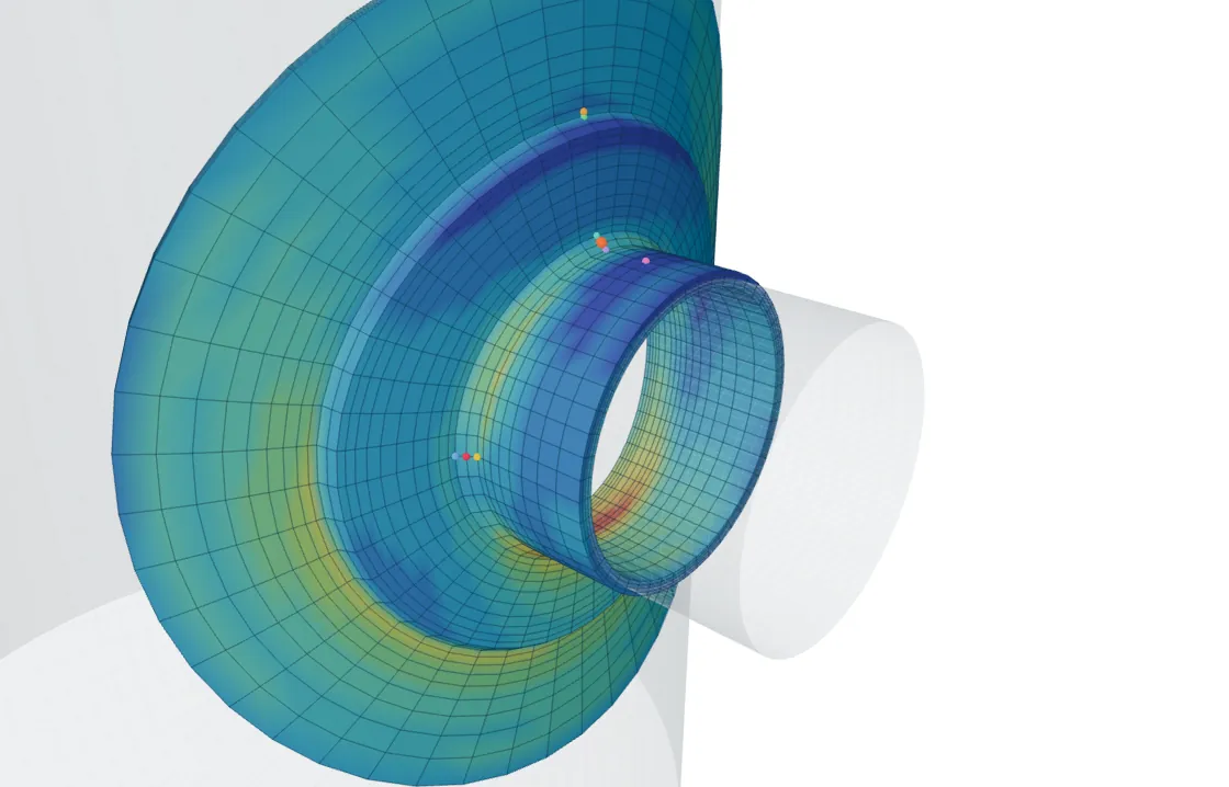
A brick (solid) model gives the full stress through the wall, not membrane and bending directly. To check it against VIII-2 limits, the stress along a stress classification line (SCL) across the wall is split into membrane, bending and peak, as Annex 5-A describes. The brick model is driven at its cut faces by the shell model's motion, with the pressure on its wetted faces.
Linearising a line
Each line is sampled at 41 points; the stress tensor at each point is found from the bricks round it. In the line's own axes (1 through the wall, 2 along the wall, 3 hoop) every component is linearised on its own:
The equivalent stress of the membrane tensor is PL (or Pm), of membrane plus bending at each end PL+Pb, and of the total the peak value for fatigue.
The five Annex 5-A.3(c) checks
The Annex gives qualitative guidelines for a line whose membrane and bending can be trusted. The code reads each as a number and flags a line that breaks one, with the reason and where to move it. A flag is not a refusal: the engineer decides, moves the line, or runs limit load.
- Orientation, (c)(1): the line should be normal to the mid-surface. Flagged when the angle to the surface normal at either end is above 10°, when an end is off the model's surface by more than 5 % of the line, or when the two surfaces are not parallel (a taper or a weld face).
- Monotonic, (c)(2) and (5): the hoop and meridional stresses should rise or fall steadily. Read on the line less 10 % at each end; the part that runs against the trend, (Σ|Δσ| − |σ_end − σ_start|)/2, is flagged above 10 % of the dominant stress.
- Through-thickness, (c)(3): σ11 should be monotonic and equal the surface pressure at both ends (−p wetted, 0 free), within 15 % of the dominant stress. Only on a line normal to parallel surfaces.
- Shear, (c)(4): σ12 should be below 20 % of the dominant stress, or near zero at both surfaces (below 30 % of its largest value). Only on a line normal to parallel surfaces.
- Discontinuity, 5-A.3(a): an end within a quarter of the wall of a listed weld toe or wall corner, with a surface peak more than 25 % above the linearised membrane plus bending there. The line then runs through the notch, and its bending depends on the mesh. On a model with no list, a peak above 50 % is flagged on its own.
The monotonic check by hand, hoop stress along a line (illustrative values, MPa)
| Samples (ends trimmed) | 160, 150, 120, 125, 40 |
| Σ|Δσ| | 10 + 30 + 5 + 85 = 130 |
| |σ_end − σ_start| | |40 − 160| = 120 |
| Against the trend | (130 − 120)/2 = 5 MPa |
| Dominant stress | 160 MPa; 5/160 = 3 %, below 10 %: no flag |
The values are made up to show the arithmetic; they are not from a model.
Placing your own line
Besides the lines the tool places, the engineer can click through the wall on the results view, or type the ends. A line is refused, with its reason, when an end is off the surface, when it leaves the metal, when it crosses two walls (the shell and the nozzle, say; a pad counts as part of the shell wall), or when it is outside 50 to 150 % of the wall thickness measured along the surface normal. Two lines with both ends within 0.5 mm of each other are warned about as the same section read twice. The report lists these lines in their own table, each with its Annex check.
σ1+σ2+σ3 against each component's own S
The local failure check of VIII-2 5.3.2 limits the sum of the principal stresses of membrane plus bending to 4S. On the shell model the sum is the trace of the membrane-plus-bending tensor, on the larger face. On the branch, each part is read against its own S: the shell, the nozzle, the pad and each attachment with its own material. A part with shell and pad through the wall takes the lower of the two, and a node where two parts meet (the junction line, a pad edge) the lowest of them all. On a brick SCL, the line is read against the lowest S of the parts it crosses. With one material everywhere the check is unchanged.
A node on a pad edge, shell S 138 MPa, pad S 118 MPa (example values)
| σ1+σ2+σ3 at the node | 400 MPa |
| Read against the shell | 400/(4·138) = 400/552 = 0.72 |
| Read against the lowest S | 400/(4·118) = 400/472 = 0.85: this governs |
Where it stops
- The thresholds (10°, 10 %, 15 %, 20 and 30 %, a quarter wall, 25 %) are the tool's reading of the Annex's qualitative words; the report states them. The owner is to confirm them.
- A flagged line still gets its numbers. The flag says the split into membrane and bending may not mean what the limits assume there.
- A line through a weld's notch reads mesh-dependent bending. Move it about half a wall thickness away, or read the total stress there as peak.
- Brick results are early access, under verification, like the rest of the FE half.