Being added. Courses, the shell below a head, tapers and insert plates are on a branch of the FEA workbench (ajay/shell-courses-insert, 2026-10-31), not in the released tool yet. The released shell model has one wall thickness per parent.
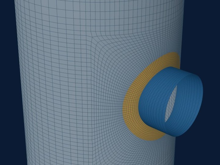
A real shell is seldom one plate. Courses of different thickness meet at girth seams, a head sits on a short shell of its own thickness, and a nozzle may sit in a thicker insert plate. A shell model has one surface of nodes. The code keeps that one surface and gives every other plate its own thickness and a section offset, so each plate's mid-surface sits where it really is.
One node surface, offsets for the rest
The node surface is the corroded mid-surface of the reference segment: the course that holds attachment 1, or the head. Corrosion comes off the inside, so the corroded mid-surface of a plate of nominal thickness t and inside radius Ri lies at Ri + (t + ca)/2. Every other plate lies off it by an offset (+ outward) set by how the plates line up.
The offset is not cosmetic. Where the membrane force N passes from one mid-surface to the other it acts with a lever arm e, so the seam carries a bending moment N·e. That bending adds to PL+Pb+Q near the seam.
The UW-9(c) taper
VIII-1 UW-9(c) asks for a taper where butt-welded plates differ in thickness by more than the lesser of a quarter of the thinner plate and 1/8 in. (3 mm). The taper is at least three times the offset between the surfaces. The code models it on the thicker plate, next to the seam, as element rows whose thickness and offset step evenly from the thin plate to the thick one, each row a part of its own.
Below the trigger the step is plain. Its offset is modelled only where the seam lies within 2.5√(R·t) of an attachment's footprint, where the N·e bending reaches the junction. Elsewhere it is ignored and a note says so. The mesher puts a grid row on every seam and taper edge, stops a nozzle's refined block at the nearest seam, and refuses a seam that runs through an attachment's footprint, giving the clearance needed.
Two courses, inside diameter 2000 mm, 20 mm below the seam, 28 mm above, inside flush
| Trigger | min(20/4 = 5, 3) = 3 mm; the difference 8 mm is past it: taper |
| Taper | L = 3·8 = 24 mm on the 28 mm course, above the seam |
| Rows | √(R·t) ≈ √(1010·20) = 142 mm; 24/(0.25·142) = 0.68, rounds to 1; at least 2 rows of 12 mm |
| Row thickness | at the row centres, a quarter and three quarters along: 20 + 8·0.25 = 22 mm and 20 + 8·0.75 = 26 mm (nominal; corroded less ca) |
| Offsets from the 20 mm course | (22 − 20)/2 = 1 mm, (26 − 20)/2 = 3 mm, the full 28 mm course (28 − 20)/2 = 4 mm |
| A 20 to 22 mm seam instead | 2 mm ≤ 3 mm: plain step, 1 mm offset modelled only within 2.5·142 = 355 mm of an attachment |
Insert plates
An insert plate replaces the shell round a nozzle with a thicker plate; it is not added to the wall as a pad is. It may be round or rectangular (square corners in the model), lines up inside flush, outside flush or centred, and takes the pad's material. Where it is thicker than the shell round it by more than the trigger, the 3:1 taper sits on the insert, inside its own outline. Its outline is read as a weld line and named "Insert plate edge" in the results, with no fillet leg stepped off, as at a butt weld.
Round insert, 40 mm thick, in a 20 mm shell of inside diameter 2000 mm
| Taper | 40 − 20 = 20 mm > 3 mm: 3·20 = 60 mm on the insert, inside its outline |
| Edge distance warning | √(R·t_ins) ≈ √(1020·40) = 202 mm: an insert edge closer than this to the nozzle is warned about |
Where it stops
- No UG-37 or VIII-2 4.5 area credit is computed for an insert: the model takes it as geometry only. Area replacement is a separate check.
- A pad and an insert on one nozzle are not taken, nor an insert with gussets.
- Fabrication misalignment within UW-33 is not modelled; only the nominal offsets from the chosen alignment are.
- An insert edge closer than √(R·t_ins) to the nozzle is warned about, not refused; the owner is to confirm.
- A check against the hand solution for a two-course cylinder under pressure, recorded on the branch: radial growth within 1 %, axial moment within 3 % of its peak at a mesh size factor of 0.5.