A radial load or a moment on a cylinder does two things to the shell. It bends the wall locally, and that bending dies out within a few times √(R·t) of the joint; it also squashes the whole circular section into an oval, and the oval reaches much further along the vessel, of the order of R·√(R/t).
Below are the two reaches in simple drawings, what stops the oval, and what that means for real vessels and for a shell model.
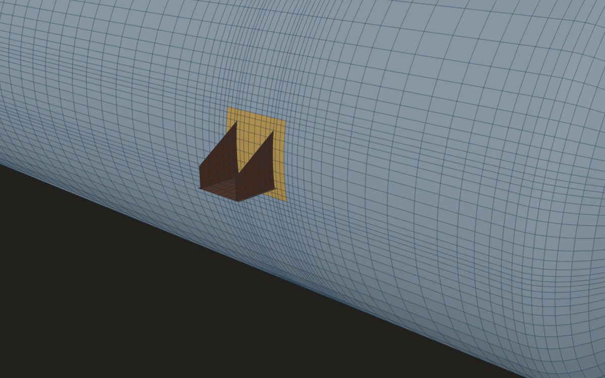
Two reaches of one load
Push on a nozzle and the shell round it carries the load in two ways at once. Close to the joint the wall bends through its thickness, like a beam on a soft foundation. This local response fades along the shell as a wave that shrinks quickly:
At 2.5·√(R·t) the envelope is down to about 4 % of its value at the joint. That is why local stress checks and the zones round attachments are sized in units of √(R·t).
The second response is easier to see end on. A slice of the cylinder is a ring, and a radial load on one side of it, or a moment in its plane, tries to change its shape from a circle to an oval. The shell resists that too, but by a much softer mechanism, so the oval reaches much further than the bending.
The ring: squashed into an oval
Take a thin ring of mean radius R and push it with two equal and opposite loads P across a diameter. It flattens along the loads and widens across them, following cos 2θ round the ring: two lobes in, two lobes out. Classical ring theory gives the bending moment and the change of diameter:
The shortening grows with R³ and falls with t³, so a large, thin ring is very soft. A ring cut from a shell is not free, though. It is joined to the rings on either side, and they must oval with it, so the wall along the vessel bends and stretches to resist the change. That shared resistance is what limits ovalisation in a real cylinder.
How far each response reaches
Local bending is resisted by the wall bending through its own thickness, with hoop stretching as the foundation. Ovalisation is resisted by long strips of wall along the vessel, which have to bend and stretch along the axis so that each ring can be a different shape from its neighbours. That action is much less stiff, so the disturbance spreads much further. A useful order of magnitude:
Measured in units of √(R·t), the reach of ovalisation is about R/t. For a thick shell the two lengths are not very different. For a thin one, the oval runs on for several diameters.
| Wall t | √(R·t) | 2.5·√(R·t) | R·√(R/t) |
|---|---|---|---|
| 10 mm | 100 mm | 250 mm | 10,000 mm |
| 20 mm | 141 mm | 354 mm | 7,071 mm |
| 40 mm | 200 mm | 500 mm | 5,000 mm |
A radial force and a circumferential moment oval the section most, and both depend strongly on how far away the shell is held round. A longitudinal moment pushes one side of the patch in and pulls the other out along the axis, so its effect stays more local. Internal pressure puts the wall in hoop tension, which resists any change of shape.
Rings and heads hold a section round
The oval stops where something stiff all the way round the circumference holds the section round: a head, a stiffening ring, a tray-support ring, a cone junction, a tubesheet or a thick flange. These are the shell's lines of support. Lugs, legs and clips do not count. They touch the shell at a few points and do not stop it going oval.
Other attachments nearby matter in proportion to their stiffness. A small nozzle or a clip has little effect on the oval. A large nozzle or a reinforcing pad stiffens the shell locally and changes it. A ring or a head close by is a line of support, and the shell between the two lines is what ovals.
A vertical column and a horizontal drum
On a vertical column the heads, tray-support rings and stiffening rings usually sit close together. Each stretch of shell between them is short and held round at both ends, so a local load cannot oval it far. The bending of the whole column under wind or earthquake is a separate, global effect, checked on its own.
A horizontal drum is the opposite. Its heads are far apart, usually with no rings between them, so the oval from a nozzle load can run a long way, and the real tangent-to-tangent length sets it. The weight of the contents also ovals the shell near the supports, where the reactions push up on the bottom of a ring that is otherwise free to change shape.
What it means for a shell model
A shell model is cut off at some length, and where it is supported its end is usually held round. If that cut is much closer than the ovalisation length, the model behaves like a shell with a ring pushed up to the attachment. It is stiffer than the vessel: it reads the junction stresses under a radial load or a circumferential moment too low, and under a longitudinal moment a little too high. Pressure alone is hardly affected, because its local disturbance is a √(R·t) effect.
- Model the shell out to the real heads, rings or cone junctions where they are known, and hold it round there.
- Where they are not known, make the model long compared with √(R·t), long enough that a longer one changes nothing material.
- Never model past a real head or ring: beyond it the model would be softer than the vessel.
- Below a head, keep at least 2.5·√(R·t) of attached shell, and more for a large attachment near the knuckle.
Key points
- A local load bends the wall near the joint and also tries to oval the whole section.
- Local bending fades within a few √(R·t); ovalisation reaches a length of the order of R·√(R/t).
- In units of √(R·t), the reach of ovalisation is about R/t, so thin shells feel it several diameters away.
- Radial forces and circumferential moments oval the shell most; longitudinal moments much less.
- Heads, stiffening rings, tray-support rings and cone junctions hold the section round; lugs and legs do not.
- A shell model should reach the real lines of support, or be long enough that their position no longer matters.
Where this matters in practice
- Large nozzles on thin shells, where ovalisation is a large share of the response to a radial load.
- Lugs, legs and support brackets that push radially on the shell.
- Choosing the length of a shell model, and whether its ends should be the real heads or rings.
- Tall columns, whose rings and heads sit close, against horizontal drums, whose heads are far apart.
- Horizontal vessels on supports, where the section near the supports ovals under the weight of the contents.
FEXLA checks the local stress at a nozzle from the forces and moments you enter, and shows each step of the working.
See the nozzle checkRelated principles
- Local loads on pressure vessel shellsHow a shell carries a push and a bend at a nozzle, how far the stress reaches, and how it splits through the wall.7 min read
- Membrane and bending in a shellWhy a curved wall carries pressure by stretching, where it has to bend, and how the two are told apart.5 min read
- Pressure stiffening and softeningTension stiffens a wall against sideways loads and compression softens it: what pressure does to a shell's stiffness.5 min read
Next principle: Membrane and bending in a shell
Educational article. It explains principles and is not design guidance; follow your governing code and edition.