A vessel with a conical bottom often has its legs coped across the shell-to-cone junction, so each leg is welded partly to the cylinder and partly to the cone. That puts the leg's local load on top of the junction's own bending under pressure, where WRC 537 does not apply. The tool keeps the Moss Chapter 4 leg checks and models the whole vessel on its legs as a shell model, with the coped leg laid onto both walls.
This post covers why the junction changes the problem and what the model builds.
Two discontinuities in one place
At a shell-to-cone junction the meridian turns. Under pressure the cone and the cylinder want to grow differently, and the junction carries a ring of discontinuity moment and shear that dies away a few decay lengths √(R·t) on each side. A leg welded across that line puts its axial load, its eccentric moment and its shear into the same zone.
WRC 537 assumes an attachment alone on a cylinder, far from any other discontinuity. Neither holds here. When part of a leg's attachment is on the bottom closure, the tool gives no WRC 537 rows and says that the shell model gives the local stress.
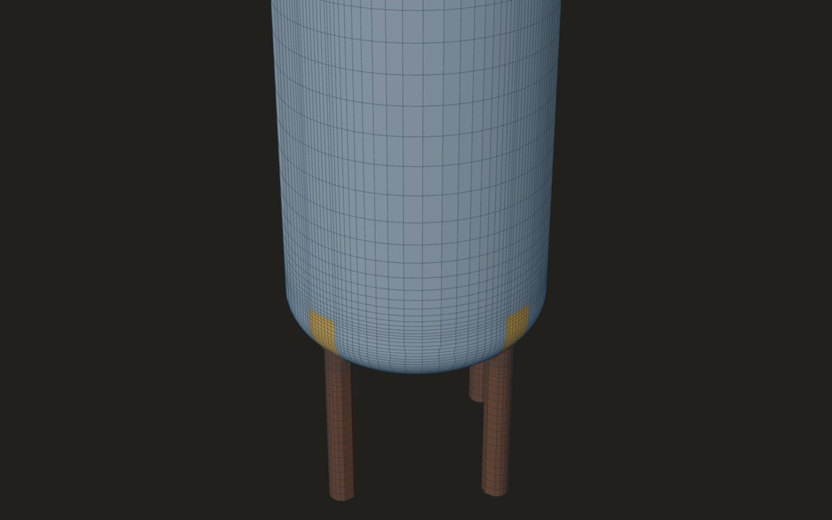
Where a leg can stand
- On its face: the leg's contact face on the shell's outside at the bottom of the attachment, with a pad under it if one is given. This is the plain leg on the cylinder.
- Across the junction: the leg's centroid on the vessel's outside diameter, the part inside cut and coped to the cone or head. Its weld runs down to where its innermost line meets the closure.
- Wholly under the head: the centroid at a given radius from the axis, the leg's top coped to the head's profile.
The Moss Chapter 4 checks of the leg, the bracing, the base plate and the anchor bolts are the same in every position. What changes is the shell under the leg.
The loads are the same as for any vessel on legs: the empty, operating and test weights with their centres of gravity, and wind and seismic as a base shear and an overturning moment from the site calculation. The model carries the operating pressure as well, so the cone junction's own bending under pressure is in the same run as the legs' loads.
How the model builds a coped leg
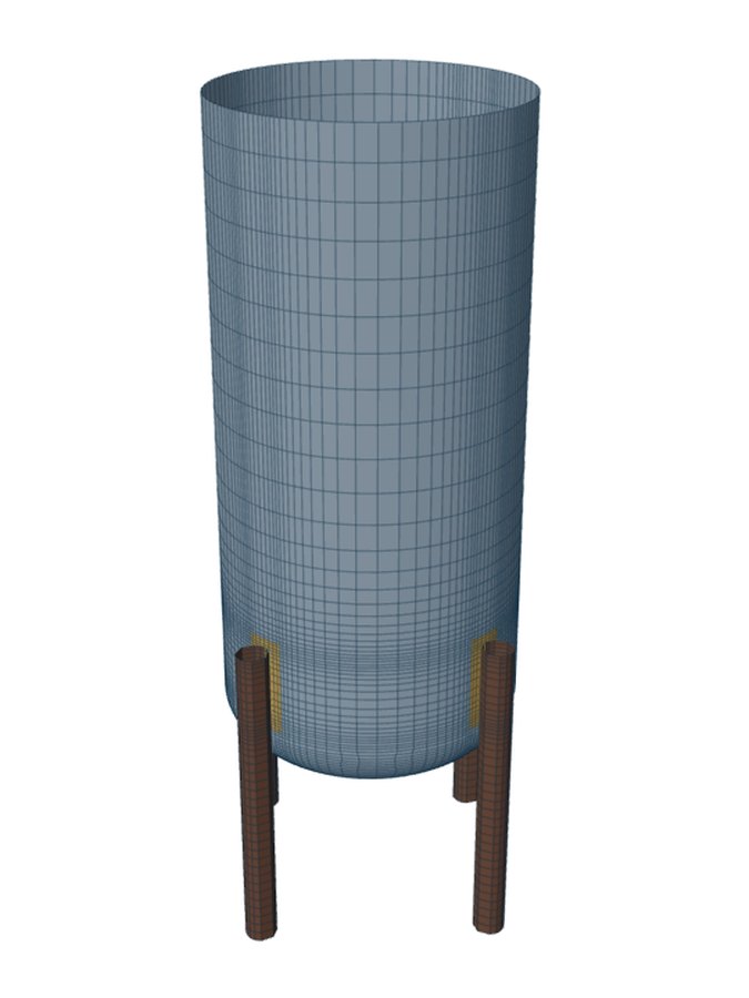
The whole vessel of revolution is one mesh: the bottom closure, the straight flange and the cylinder up to its top tangent line, on identical legs equally spaced round it, three, four, six or eight of them. Each leg is a set of vertical lines from the floor to the top of its attachment, so a plate, an angle, a channel, an I or a tube is built from its own plates.
- Within the attachment zone a leg line that would pass inside the wall is laid onto the wall instead and shares the wall's nodes. That is the cope: the leg follows the cylinder, then the cone, along its weld.
- A flange lying flat on the wall becomes a thickened patch of wall with its edges welded, as a pad does.
- The cone's mid-surface meets the cylinder's at the junction; there is no knuckle.
- The legs' feet are held directly, pinned or fixed; base plates and braces are not meshed.
Reading the result
The shell next to every leg's weld is read as the attachment zone, and the leg plates away from their weld as general membrane. Because the junction is in the same mesh, its pressure bending and the leg's local bending come out together, not as two numbers to be added by hand.
Look at the result on both sides of the junction line. A leg coped across it can put its peak on the cylinder just above the junction, on the cone just below, or at the weld end where the leg's innermost line meets the cone, and which one governs depends on the leg section, its eccentricity and the cone angle. The model reports the worst point, wherever it falls.
The same model runs a buckling check, since a leg pressing on a thin cone or shell can also cause local buckling. A top platform on legs can be modelled the same way across a top shell-to-cone junction; legs across a shell-to-head junction at the top are refused.
Where it stops
- 01Identical legs, equally spaced. Braces and base plates are not meshed.
- 02The cone meets the shell without a knuckle.
- 03A tubular leg meeting the closure is joined along lines a mesh size apart, close to a line weld but not a continuous intersection.
- 04The shell model is early access and under verification.
Try it in FEXLA
The Vessel on legs card runs the Moss Chapter 4 checks and builds the shell model for legs coped across a cone or head junction.
Open the cardReferences
- D. R. Moss and M. Basic, Pressure Vessel Design Manual, 4th ed., Chapter 4 (legs, base plates, anchor bolts).
- WRC Bulletin 537, which does not apply on the closure.
Method notes this draws on
Next post: A horizontal vessel on four support lugs: the load share
Educational article. It explains principles and is not design guidance; follow your governing code and edition.