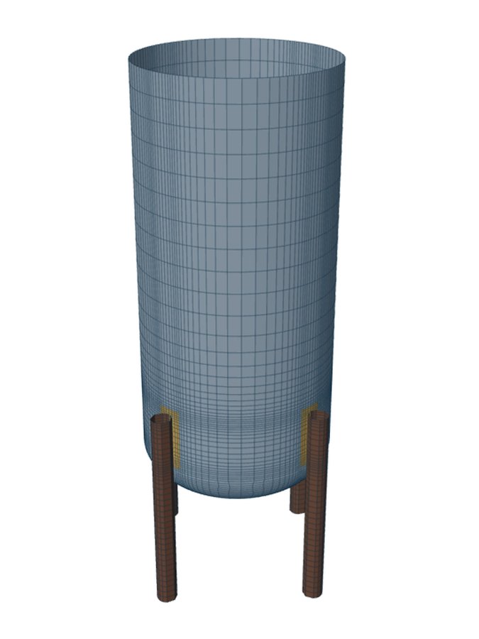
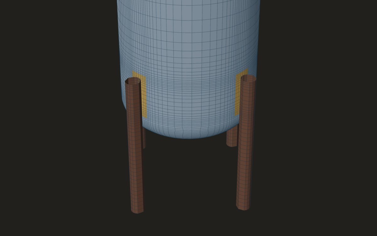
The leg checks of Moss Chapter 4 size the leg, its base and its bolts, but the shell where the leg is welded needs a local stress check of its own. For a leg on the cylindrical shell, the tool hands the governing case to WRC 537 as a rectangular clip of the leg's footprint, with two rows: the most loaded leg in line with the lateral load, and the leg at 90° to it. The loads in each row follow from the leg's axial load, its eccentricity and the shear it carries.
This post goes through how each WRC 537 load is formed.
The loads in the leg
The Moss check gives each leg an axial load and a shear for every case. The vertical share follows Moss Table 4-11, exact for any leg count and either load direction; the largest is f1 = Fv/n + 4·M/(n·d). The horizontal shear goes to the legs by their stiffness across the load. The legs are taken as pinned at the base and fixed at the vessel.
Two lengths turn those into moments at the weld. The eccentricity e is the radial offset of the leg's centroid from the shell's mid-surface, so the axial load bends the shell by Fn·e. The free length ℓ runs from the base plate to the bottom of the attachment, so a leg that is fixed at the vessel and pinned at its foot carries a moment V·ℓ at its top.
The two rows
- The most loaded leg, in line with the lateral load: its axial load as the longitudinal shear VL, the shear in line with the load as the radial load P, and ML = Fn·e + V·ℓ.
- The leg at 90° to the lateral load: its dead-load share as VL, the shear it takes round the shell as VC, and MC = V·ℓ, with ML from its own eccentricity.
- Torsion is zero in both rows. Loads are magnitudes at the junction, from the case with the largest leg load.
With braced legs the lateral shear goes through the braces, and the legs carry no shear-times-length moment. The two rows then carry only the axial loads and the moments from eccentricity.
The footprint
The leg is entered as a rectangular clip: its contact width on the shell round the circumference, and its welded length along the shell. A pad under the leg is the second rectangle, checked at its own edge on the shell thickness alone. A tubular leg touches the shell along a narrow strip, so its footprint can be long and thin. Check that its sides stay within the 1/4 to 4 range of the clip curves; outside it the calculator reads the curves at the limit and says so.
Shell compression above the leg
Beside the WRC 537 rows the hand check gives the shell's compression above the most loaded leg, fc = f1/(L1·t), with L1 the leg's width on the wall plus 2√(R·t), and the general compression from weight and moment at the attachment. Both are compared with the allowable compressive stress, factor B, which the engineer reads from the material chart in their own copy of ASME Section II Part D.
When the leg is not on the cylinder
WRC 537 takes a clip on a cylindrical shell only. If any part of the attachment is on the bottom head or cone, the tool gives no WRC 537 rows and says so: the shell model gives the local stress there. That covers legs coped across the shell-to-head or shell-to-cone junction and legs wholly under the head.
Where it stops
- 01WRC 537 rows are given for a leg on the cylindrical shell only.
- 02Wind and seismic loads are yours to give; they are not derived here.
- 03Torsion at the leg is taken as zero in the WRC 537 rows.
- 04The shell model of the vessel on its legs is early access and under verification.
Try it in FEXLA
The Vessel on legs card runs the Moss Chapter 4 checks and passes the governing leg's loads to WRC 537 at the shell.
Open the cardReferences
- D. R. Moss and M. Basic, Pressure Vessel Design Manual, 4th ed., Chapter 4: 4-4 (unbraced legs, Table 4-11).
- WRC Bulletin 537.
Method notes this draws on
Next post: Legs at the shell-to-cone junction
Educational article. It explains principles and is not design guidance; follow your governing code and edition.