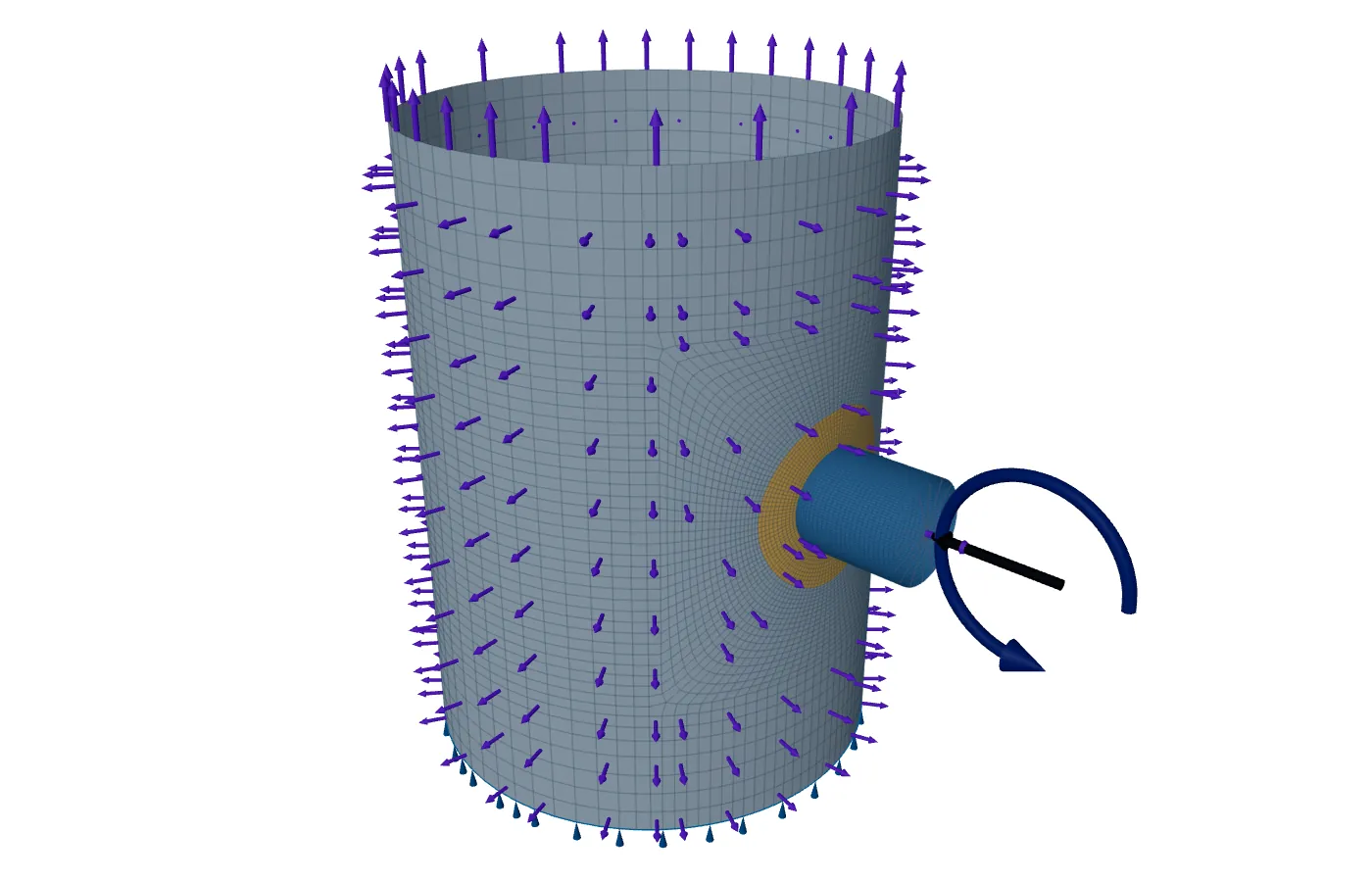
Internal pressure puts the shell in tension, and that tension can cancel part of the compression a nozzle load causes. With the pressure off, the load's stress stands alone and can be the larger, so ASME Section VIII Division 1, Appendix 46-4(c)(1) asks for cases with the pressure equal to zero as well.
The shell model in FEXLA adds those cases by itself. In the WRC 537 calculator today it is a second run, and this post shows why it is worth doing.
Pressure and load stresses have signs
Internal pressure gives membrane tension in the shell, hoop and longitudinal, at every point. The stresses from nozzle loads have both signs. A moment puts tension on one side of the nozzle and compression on the other. Bending puts tension on one face of the wall and compression on the other. A radial load that pushes the nozzle into the shell puts the shell round it into membrane compression.
Where a load stress is tensile, pressure adds to it and the case with pressure is the worse one. Where it is compressive, pressure takes away from it, and the case without pressure can be the worse one. The point that governs, and the check that governs, can change between the two.
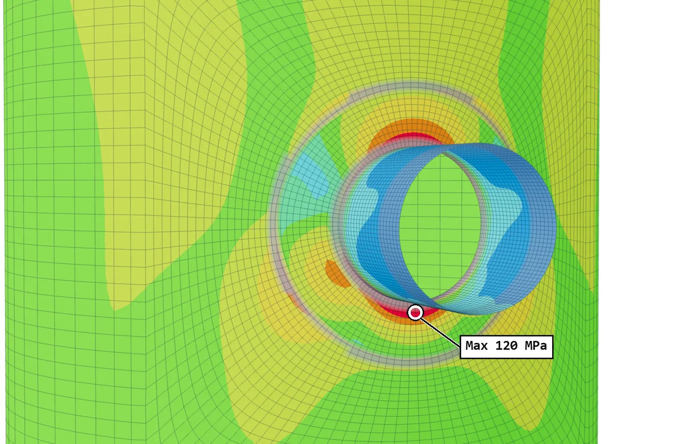
One point, with and without pressure
The same load is four times as severe without the pressure. On the far side of a moment the opposite holds: load tension adds to pressure tension, and the case with pressure governs. Neither case is always the worse one, so both are run and the worse governs at each point.
A vessel does spend time like this. At shutdown or before it is pressurised, the weight of the connected line still hangs on the nozzle. A check made only at design pressure has assumed that the pressure is always there to help.
What the code asks
Division 1 has no rules of its own for local loads. Through U-2(g) and Mandatory Appendix 46 it uses the design-by-analysis rules of Division 2, Part 5 with the Division 1 allowable stress. Appendix 46-4(c)(1) adds cases with the pressure equal to zero to the load combinations. Appendix 46-4(b) also says the 1.2 increase for wind or earthquake, a design-by-rule allowance, does not apply.
What the shell model runs
The shell model is linear. Pressure is solved once as its own basic case, so a combination without it costs nothing more than an addition. It adds a zero-pressure twin to every combination that has both a pressure and a load:
| Case | What is in it | Added when | Checked as |
|---|---|---|---|
| SUS0 | Weight D, with P = 0 | There is weight and a design pressure | Primary |
| OCC0 | D plus wind or earthquake, with P = 0 | There is an occasional row and a pressure acting with it | Primary |
| OCCL0 | D plus 0.75 × occasional plus 0.75 × operating, with P = 0 | As OCC0, with load-controlled operating loads | Primary |
| OPE0 | D plus operating loads and thermal state, with P = 0 | There are operating or thermal loads and an operating pressure | Range from shutdown against SPS |
The range from shutdown matters as much as the primary checks. Where the operating loads give compressive stress, the range to the operating state without pressure can be the larger, so OPE0 can govern the primary plus secondary check.
The other analyses follow the same rule. Limit load runs its combinations with the pressure not acting as well. Buckling runs each combination with the pressure not acting, since internal pressure's tension also offsets the compression that buckles a shell.
In the WRC 537 calculator
The calculator checks one load set at the design pressure entered. It adds the pressure stress at every point, raised at the nozzle edge by the pressure stress intensity factor of Division 2, 4.5.5. It does not add a zero-pressure case by itself.
- Run the job a second time with the design pressure set to zero, and keep both reports. With no pressure, the pressure term and its intensity factor drop out, and the load stresses stand alone.
- The option to run the radial load reversed as well changes the sign of that load only. It is not a zero-pressure case.
- The calculator's own validation includes such zero-pressure cases, called hot shut-down, because they isolate the load stresses.
Where it stops
- 01In the WRC 537 calculator the zero-pressure case is a second run by the engineer; it is not added automatically.
- 02The shell model adds a zero-pressure case only where there is both a pressure and a load to pair it with.
- 03Vacuum and external pressure are a different case: there the pressure itself compresses the shell. This post is about internal pressure.
- 04The finite-element results are early access and under verification.
Try it in FEXLA
The Nozzle loads card runs the WRC 537 check at the pressure you enter, and the shell model with its zero-pressure cases added.
Open the cardReferences
- ASME Section VIII Division 1, U-2(g); Mandatory Appendix 46, 46-4(b) and 46-4(c)(1).
- ASME Section VIII Division 2, Part 5, Table 5.3; 4.5.5 (pressure stress intensity at a nozzle).
- WRC Bulletin 537.
Method notes this draws on
Next post: How long should the shell be around a nozzle
Educational article. It explains principles and is not design guidance; follow your governing code and edition.