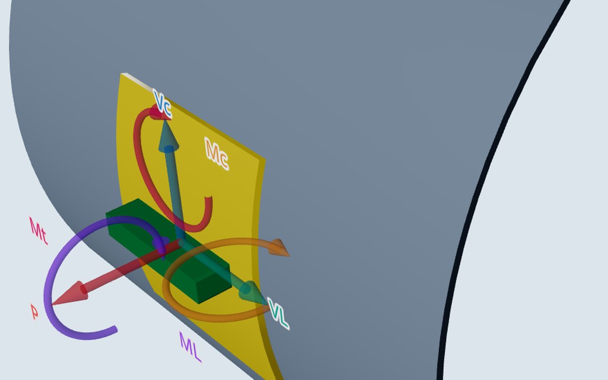
A nozzle load table often gives several sets of loads: sustained (weight), operating (thermal expansion of the connected line), and occasional (wind or earthquake). The stresses are worked out the same way for each; what changes is whether the stress is primary or secondary, so which limit it meets, and which other loads it is combined with.
This post explains what each set means for the check, in the WRC 537 calculator and in the shell model.
What each set is
- Design pressure with sustained loads: pressure and the weight of what the nozzle carries. These must be carried whatever the shell does. Primary.
- Operating: usually the thermal expansion of the connected line, an imposed movement. It relaxes once the metal yields locally. Secondary, judged by its range from shutdown to operating. A load that must be carried while running, such as an agitator's thrust, is load-controlled and primary instead.
- Occasional: wind and earthquake inertia, primary but short-lived. A seismic anchor movement or a support settlement is an imposed displacement, secondary.
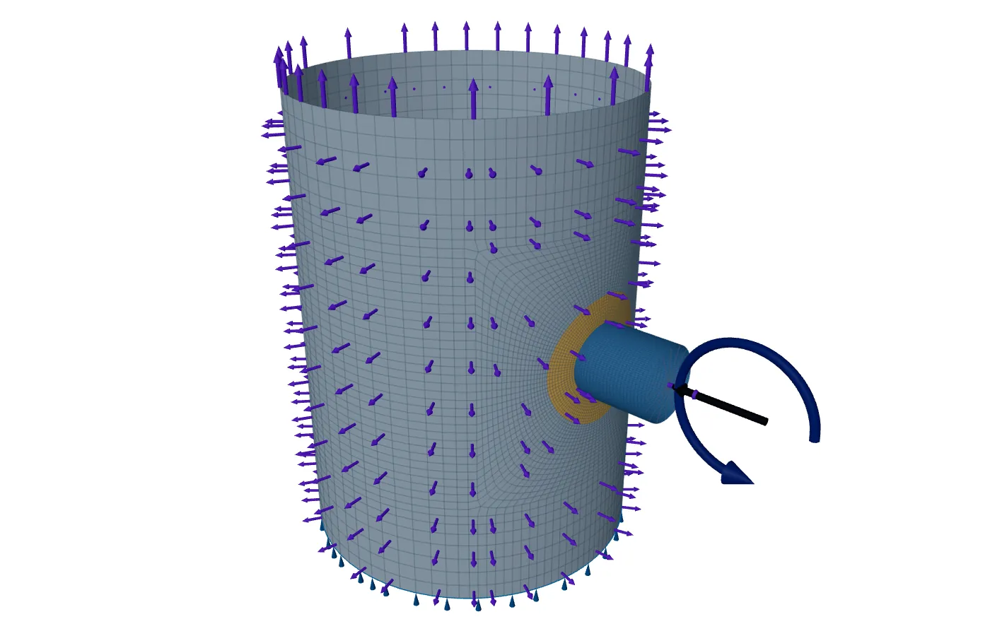
In the WRC 537 calculator
The calculator runs one set of loads at a time and checks it twice: the membrane stress against 1.5S, and the surface stress (membrane plus bending) against a design factor times S. The factor is the choice that follows the load set.
- 3.0, the default: the loads ease as the shell deforms, as an imposed displacement does. The surface stress may reach 3S.
- 1.5: the loads are sustained (weight, pressure thrust, wind, seismic). The surface stress is limited like a primary stress, to 1.5S.
- A value between 1.5 and 3.0, entered by the engineer, only where the design basis supports it, for example a set that mixes sustained and self-limiting loads.
The membrane check stays at 1.5S whatever is chosen. To check a load table with three sets, run it three times with the matching factor and file the three reports; the defaults are fixed so that a result is comparable between users.
In the shell model: load rows
The shell model takes the sets as rows on each attachment: weight (D), operating, and occasional, with pressure and the metal temperatures as separate inputs. The model is linear, so each basic case is solved once and the combinations are added up. Each combination then meets the checks that fit what is in it.
| Case | What is in it | Checked as |
|---|---|---|
| SUS | Design pressure + D (+ L if the operating row is load-controlled) | Primary: Pm ≤ S, PL ≤ SPL, local failure |
| OCC | ΩP·P + D + (0.6W or 0.7E) | Primary, as SUS, no increase in the limit |
| OPE | Operating pressure + D + operating row | PL + Pb + Q range from shutdown ≤ SPS |
| SUS0, OPE0 | The same with pressure at zero | As above |
The zero-pressure cases matter. Pressure can lower the stress a nozzle load causes at some points, so a load can govern on its own. Division 1 Appendix 46-4(c)(1) asks for cases with pressure equal to zero, and the model adds them whenever there is pressure and an attachment load.
Occasional loads: basis and direction
Wind and earthquake values often come from a structural calculation at strength level. ASME Section VIII Division 2 Table 5.3 takes 0.6W and 0.7E in the elastic combinations. The engineer says which basis the row is on: wind or earthquake at strength level, or already at allowable-stress level, taken at 1.0. With a load-controlled operating row the model also runs Table 5.3 combination (7), with 0.75 on the occasional and the operating rows.
Wind and earthquake act from either side. With the reversal option on, every combination with the occasional row is also run with the row negated. An occasional row entered as an imposed displacement is checked as a range of twice its value instead.
Operating loads that reverse
Some operating loads change sign: a rotating bending moment, or a line that moves one way when hot and the other when cold. With the reversal option on, the model runs the operating case with the row negated as well, and the range between the two, twice the row. The largest of the three governs the primary-plus-secondary check.
Buckling and limit load use their own factors
The buckling check runs the combinations of Table 5.15, with 0.88 on pressure and dead load and 0.71 on wind or earthquake at strength level. The limit-load check runs the factored combinations of Table 5.4, such as 1.5(P + D), each as its own load path from zero, because plastic results cannot be added up. In both, the factors sit inside the combination, so the result is a margin on the combination as it stands.
Where it stops
- 01Wind and seismic loads are not derived here; they are yours to give, with the basis they are on.
- 02The WRC 537 calculator checks one set per run; it does not combine sets for you.
- 03A connected line's flexibility, and how the nozzle's stiffness changes its loads, are not computed. The loads are taken as given.
- 04Finite-element results are early access and under verification.
Try it in FEXLA
The Nozzle loads card takes a load table and checks it with WRC 537 or the shell model, with the surface limit or the load rows set as described here.
Open the cardReferences
- ASME Section VIII Division 2, Part 5: Table 5.3 (load combinations), Table 5.4 (limit load), Table 5.6 (classification), Table 5.15 (buckling).
- ASME Section VIII Division 1, Mandatory Appendix 46, 46-4.
Method notes this draws on
Next post: Nozzles close together
Educational article. It explains principles and is not design guidance; follow your governing code and edition.