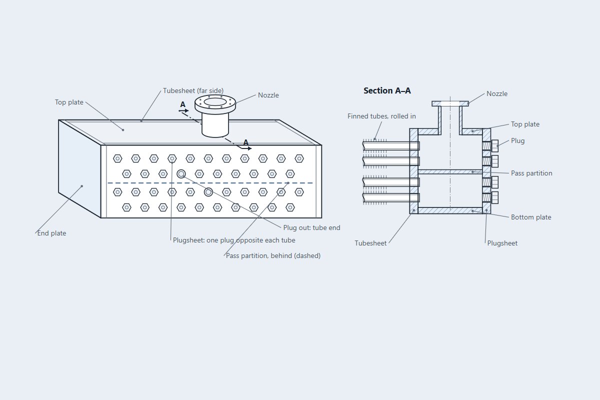
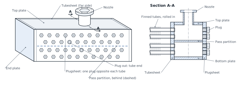
The tubesheet of an air-cooler plug header is drilled with tube holes, and the plugsheet opposite has a plug hole in line with each. Under VIII-1 Appendix 13 these rows weaken the plate in membrane and in bending by different amounts, so 13-6 gives two ligament efficiencies, e_m and e_b, from the hole profile through the thickness. The check then divides the stresses at the row by them, or keeps the joint efficiency, by the rule of 13-4(g).
This post works through the two efficiencies on a reference header and how they enter the stress check.
Where the stress at a row comes from
A plug header is a rectangular box. Its plates carry pressure as a membrane force from equilibrium and as bending, each plate a beam between corners whose moments come from the frame of Appendix 13. A hole row sits somewhere along a plate, often near midspan, and the stress there is read from the same moment line as the rest of the plate.
The hole as a stack of segments
A hole is often not one diameter through the plate: a tube hole may have grooves, and a plug hole a counterbore on the plugsheet's outside face. The row is entered as a pitch p and a list of segments from the inside face outward, each a diameter d_k over a length T_k, adding up to the plate thickness. The order matters, because bending depends on where the metal is.
Each row is placed by the distance of its hole centres from the plate's midspan, and 13-6 is applied to each row on its own, so a plate with two rows reports two pairs of efficiencies. The joint efficiency E at the row is that of a butt weld lying there, and 1.0 where there is none, as at a corner joint that is not a butt weld.
For holes of one diameter both reduce to (p − d)/p. For a stepped hole they differ: a groove near one face costs more in bending than in membrane, and moves the neutral axis.
A reference tubesheet
How 13-4(g) uses them
- Both efficiencies below the joint efficiency E: the stresses at the row are divided by e_m and e_b, and compared with the allowables using E = 1.0.
- Both at or above E: the gross stresses are compared with the allowables using E.
- One below and one above: the code is silent. By default the engine evaluates both readings and keeps the worse ratio.
- Away from the rows, on a drilled plate, the default divides the membrane stress by the plate's smallest e_m and leaves the bending gross. That reproduces the published PTB-4 example. The literal reading, dividing bending by e_b everywhere, is a selectable policy.
The allowables are S·E on membrane and 1.5·S·E on membrane plus bending of a plate. With both efficiencies near a half, the row stresses double, which is why a hole row at midspan can govern a plate whose corner looks worse on gross stress.
Corrosion comes off the inside and outside segments before the formulas run, and a segment worn away is dropped. The pressure test uses the uncorroded segments.
Every stress in the frame grows in proportion to the pressure for the plain box sketches, so the maximum allowable pressure follows directly: the design pressure times the allowable over the stress, taken at the worst row, hole rows included, then the lower of that and the end plates. In the published PTB-4 box the governing row is at midspan of the pair B plates, at 397.4 psi.
Where it stops
- 01Rows on a corner arc, and rows on the reinforced plates of sketch (4), are refused; a row on a stay is warned.
- 02No equivalent solid plate thickness is computed: the holes enter only through e_m and e_b.
- 03Nozzles and openings in the header, and nozzle loads, are not checked here.
- 04The shell model cross-check of the header is early access and under verification.
Try it in FEXLA
The Air-cooler header box card checks plug headers to Appendix 13 with the ligament efficiencies of each hole row, and runs a shell model beside it.
Open the cardReferences
- ASME Section VIII Division 1, Mandatory Appendix 13: 13-4(g), 13-6, 13-7.
- API Standard 661 (air-cooled heat exchangers), for the header type.
- ASME PTB-4, example E4.12.1.
Method notes this draws on
Next post: How WRC 537 checks a nozzle, step by step
Educational article. It explains principles and is not design guidance; follow your governing code and edition.