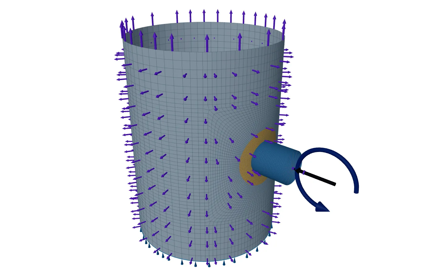
A load set is the six loads that act together in one condition, with their real signs. A load envelope takes the largest value of each load from any condition, usually without a sign, so the loads in it never act together and their directions are unknown. An envelope has to be checked as if all its values act at once, with every combination of signs.
Envelopes are common: a purchaser's standard table by nozzle size and rating is one, and so is a single line of maximum loads from the connected-line designer. This post explains what that means for the check and how to cover it with the calculator as it is today.
Set or envelope
| Load set | Load envelope | |
|---|---|---|
| Values act together | Yes | No; taken as together, to be safe |
| Signs | Known | Unknown, so all must be checked |
| Typical source | One case of the line's stress analysis | The worst of all cases, or a standard table |
| How to treat it | As its condition allows | All as primary, as a design set |
Take P = 2 kN from the weight case, ML = 5 kN·m from the operating case and MC = 3 kN·m from the wind case. Written in one row, they look like a set. They are not: they come from three conditions, and the row says nothing about which way each acts.
Why every sign matters
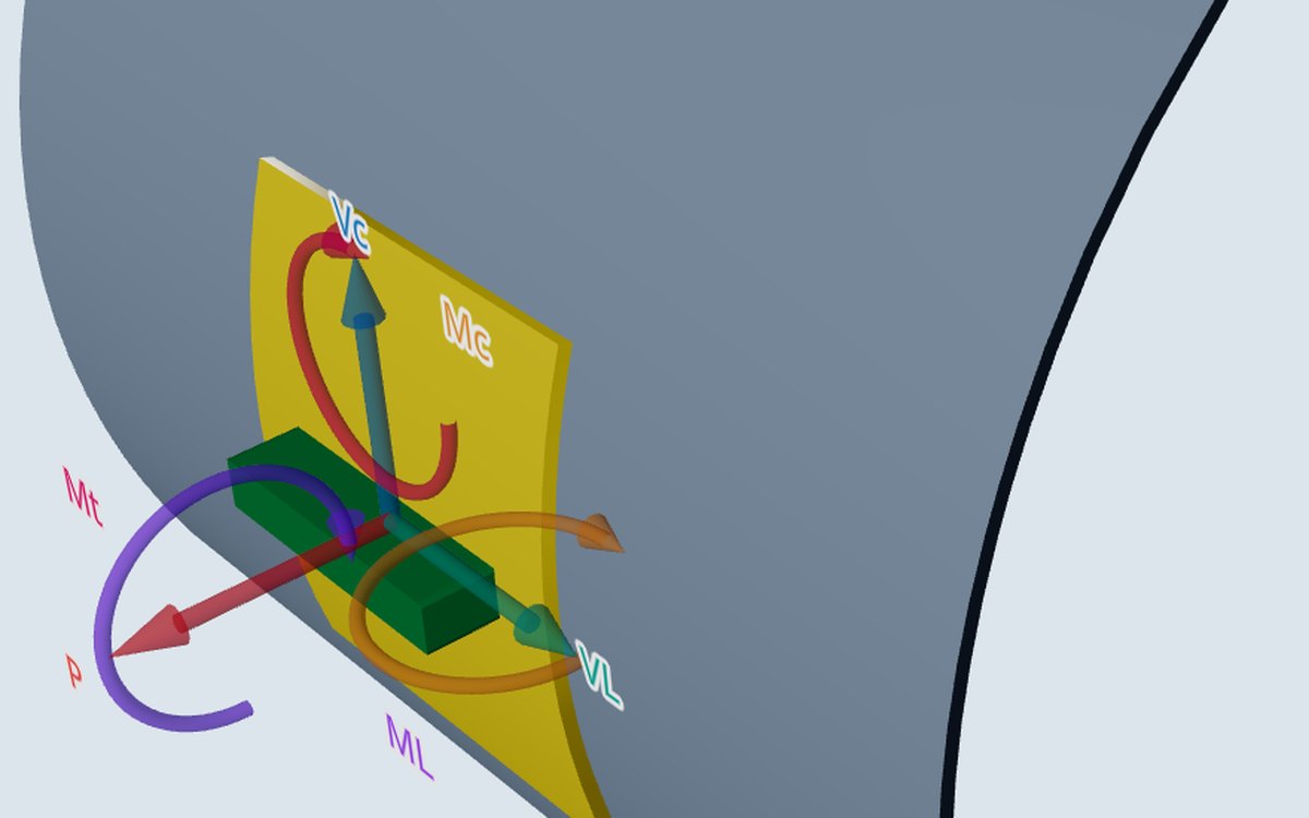
Six components, each plus or minus, give 2⁶ = 64 combinations, fewer when some are zero. Not all of them change the answer. In the calculator's sign patterns for a round nozzle on a cylinder, the radial load stresses all four points with one sign, ML gives A and B equal and opposite stresses, and MC does the same at C and D. Reversing ML only swaps what A and B see, and both are checked.
Two signs do change the answer. The sign of P changes the membrane stress at every point at once, against the pressure stress that is always there. And the shear from VC or VL adds to the torsion at one point of each pair and subtracts at the other, so the sign of MT against the shears decides which points get the larger shear.
What the calculator does with one set today
The WRC 537 calculator takes one set of six loads with the pressure, and checks the membrane stress against 1.5S and the surface stress against the design factor times S. It does not yet check every sign combination for you. It has one option for signs: a check box that also runs the case with P reversed, everything else unchanged, and gives one verdict for both.
From the sign patterns above, with the loads entered at the junction, a nozzle on a cylinder needs these runs to cover an envelope:
- Enter the six values as positive numbers and tick the reversed-P box.
- If MT and at least one shear are not zero, run again with MT negative, the box still ticked.
- Take the worse of the two verdicts.
With the loads at the nozzle end the shears also change the junction moments, ML − L·VL and MC + L·VC, so the sign of each shear against its moment matters too. Enter the shears with the signs that add to the moments, or carry the loads to the junction yourself first.
Why one plain set is conservative, and when it is not
Checking an envelope as one design set treats every load as primary. For loads that include thermal expansion of the connected line this is conservative: the code would judge that part by its range against 3S, not against 1.5S. It is not conservative the other way round. A set that holds only the weight case leaves out the thermal range, and a check of it says nothing about that range.
When an envelope fails
A failing envelope is the normal start of a conversation, not a dead end. In order:
- Report which check failed, and say that the loads were taken as an all-primary envelope.
- Ask the connected-line designer for the real cases for that nozzle: sustained, operating and occasional. The true sustained loads are often much smaller than the envelope.
- Check those as separate sets, each with the limit that fits it.
- Run the limit-load analysis in the shell model, which often shows margin the elastic check hides at the junction. It is early access, so treat a pass there as unconfirmed for now.
- Strengthen if it still fails: a pad, a thicker neck or a heavier nozzle barrel.
- Or ask for lower loads, for example that the nozzle accepts a stated share of the table loads.
Where it stops
- 01The calculator does not yet check every sign combination of an envelope; the runs above are done by hand.
- 02The two-run rule above is for a round nozzle on a cylinder with the loads at the junction; for other cases, check more combinations.
- 03Separate load sets are not combined for you; each run checks one set.
- 04The shell model has no envelope option yet, and its results are early access and under verification.
Try it in FEXLA
The Nozzle loads card checks one load set per run, with an option to run the case with the radial load reversed as well.
Open the cardReferences
- ASME Section VIII Division 2, Part 5: Table 5.6 (classification), 5.5.6 (primary plus secondary range).
- WRC Bulletin 537: Precision Equations and Enhanced Diagrams for Local Stresses in Spherical and Cylindrical Shells due to External Loadings.
Method notes this draws on
Next post: Using nozzle load tables by nozzle size and flange rating
Educational article. It explains principles and is not design guidance; follow your governing code and edition.