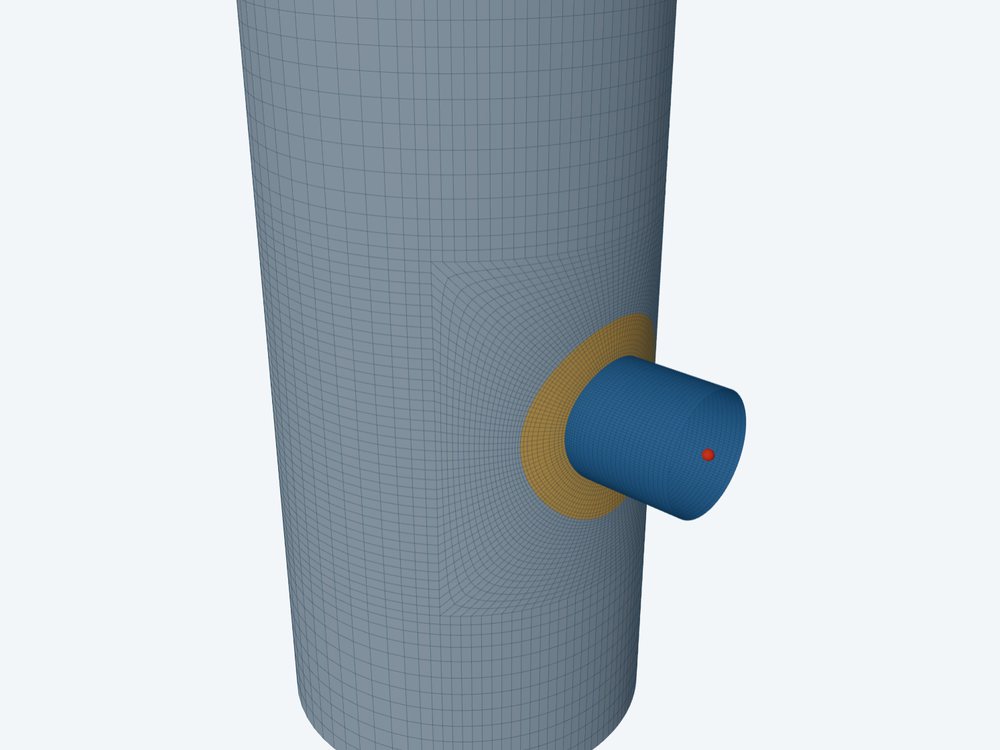
Membrane stress above the general limit S is accepted as local, PL, only if it stays in a small region. In ASME Section VIII Division 2, 5.2.2.2(b), membrane equivalent stress above 1.1S may extend no more than √(R·t) along the meridian, and separate local regions must be kept apart.
FEXLA's shell model enforces the first rule by zones, on the safe side. The second rule is not checked yet, and this post says what that means for a job with more than one attachment.
Why the extent matters
Near a nozzle the membrane stress is allowed to rise above S, to SPL: 1.5S, or the yield strength where that is higher and the ratio of yield to tensile strength is 0.7 or less. Away from it the limit is S. The higher limit rests on one argument: a small region of high membrane stress is held by the less stressed metal round it, so it cannot yield right through and keep going.
If the region is large, the argument fails: the stress is no longer held by its surroundings and behaves like general membrane stress. The region test is the code's way to say how small is small enough. A membrane stress that fails it is general primary membrane, Pm, and meets S.
The rule
- Extent: the distance over which the membrane equivalent stress exceeds 1.1S, measured along the meridian, must not exceed √(R·t).
- Separation: two local regions above 1.1S must be a minimum distance apart along the meridian, and the regions under separate attachments, such as neighbouring brackets, must not overlap where they are above 1.1S.
√(R·t) is the decay length of the shell, the same length that sets how far the bending at a junction reaches. On a large, thick shell a local region may be wider.
What the shell model does today
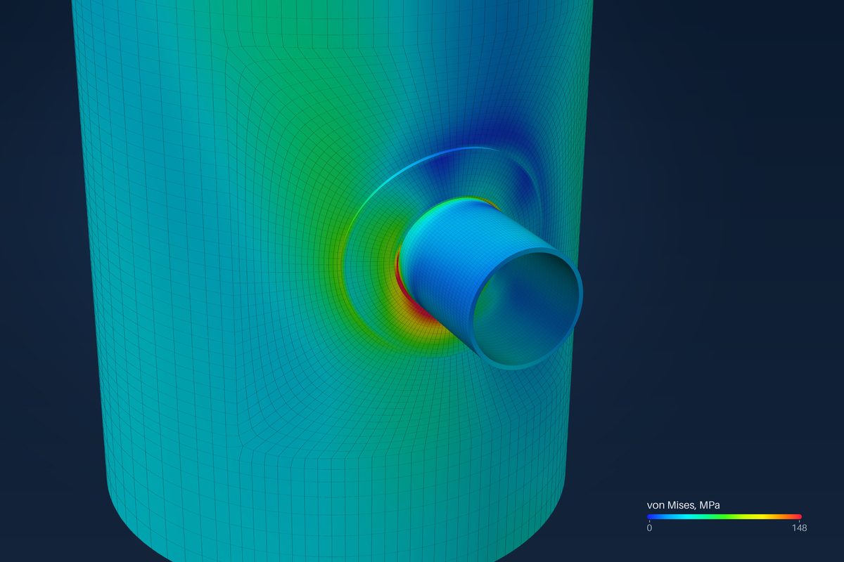
The shell model does not measure each region. It uses zones. Within √(R·t) of each weld line, on the shell, the nozzle and the attachment, the membrane is local and is checked as PL against SPL. Beyond √(R·t) it is general and is checked as Pm against S. So any membrane stress above S outside the junction zone fails, and stress above 1.1S cannot reach further than √(R·t) without failing a check.
| Zone | Membrane checked as | Limit |
|---|---|---|
| Within √(R·t) of a weld line | PL | SPL |
| Beyond √(R·t) | Pm | S |
| Knuckle of a formed head | PL | SPL |
This enforces the extent rule, with a margin: beyond √(R·t) the limit is S, not 1.1S. The report row for the outer zone says so.
When the zone method fails a case like this, the result is safe but may be pessimistic. The engineer can see the membrane equivalent stress at every node in the results and judge it against the code's rule.
What is not checked: separation
The shell model takes up to four attachments on one shell or head. The mesher refuses attachments that overlap. It does not test whether their local regions sit too close together, and the assessment checks each zone on its own. Two nozzles whose junction zones each pass can still have regions above 1.1S that run into each other.
With two or more attachments, the separation is the engineer's to check, from the membrane stress between them. Where the stress above 1.1S joins up between two attachments, treat the joined region as general membrane.
WRC 537, and what is planned
WRC 537 gives stresses only at the edge of the attachment, so it cannot measure how far a region reaches. The calculator takes the membrane stress at the edge as PL against 1.5S, and the bulletin assumes the attachment stands alone. An attachment within about 2.5 decay lengths of another is outside its range, which is the case where separation matters.
An automatic test is specified in our studies: find each region above 1.1S, measure its extent from the weld toe, measure the gaps between regions, and report both. It is not built. Until it is, the zone method above is what runs, and the separation check is done by hand.
Where it stops
- 01The separation of local regions is not checked; with two or more attachments it is the engineer's check.
- 02The extent of each region is not measured. The zone method enforces the extent rule at S instead of 1.1S beyond √(R·t), which is conservative.
- 03WRC 537 gives stresses only at the attachment edge and cannot measure a region's extent.
- 04The finite-element results are early access and under verification.
Try it in FEXLA
The Nozzle loads card runs the shell model, which checks membrane stress as PL within √(R·t) of each weld line and as Pm against S beyond it.
Open the cardReferences
- ASME Section VIII Division 2, Part 5: 5.2.2.2(a) and (b) (local primary membrane stress), eq. (5.2) SPL, Table 5.6.
- WRC Bulletin 537.
Method notes this draws on
Next post: The primary plus secondary stress range limit, SPS
Educational article. It explains principles and is not design guidance; follow your governing code and edition.