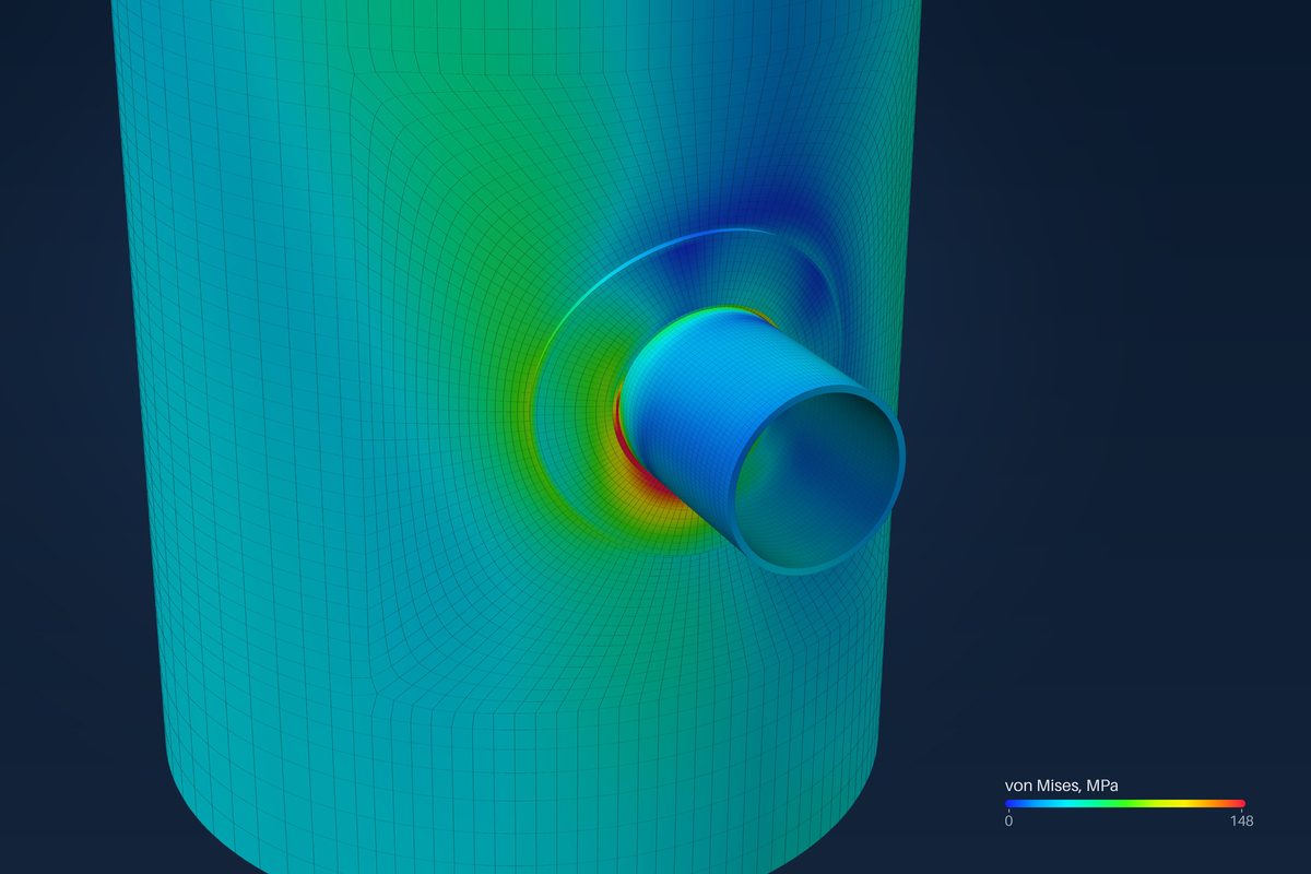
The primary plus secondary stress, PL + Pb + Q, is checked as a range over an operating cycle, against the limit SPS. In the 2025 edition of ASME Section VIII Division 2, SPS is the sum of the yield strengths at the coldest and the hottest points of the cycle, which keeps the range within what the metal can shake down to.
This post covers what the range is, how FEXLA sets SPS, and what follows when a range exceeds it.
A range, not a value
Secondary stress comes from parts that must fit together, such as the bending at a nozzle junction or a thermal gradient. If it goes above yield on the first cycle, the metal yields a little and the parts then fit with less stress. What matters is the next cycle: does the metal go back to working elastically, or does it yield again every time? That depends on the range of the stress over the cycle, not on its value at one moment.
In the shell model the range runs from shutdown, at zero load, to the operating state: operating pressure, weight, the operating loads and the thermal state. It is also run with the pressure at zero. Where the operating loads reverse, the range between the two signs, twice the load, is checked too. An imposed seismic movement is checked as a range of twice its value.
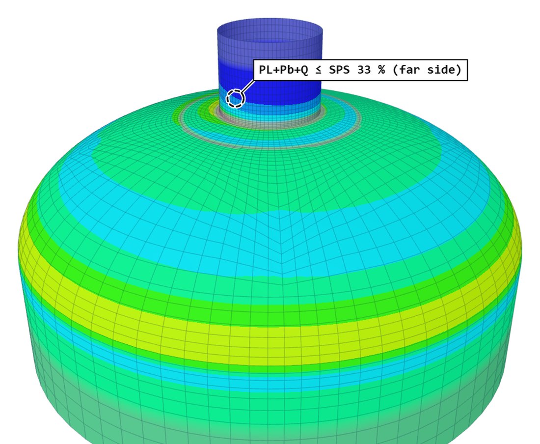
How SPS is set
- With the same yield at both ends of the cycle, SPS is twice yield.
- Where Sy/Su is above 0.7, the metal may soften under cycling, and the yield would need reducing from cyclic data. FEXLA does not assess that; it caps SPS at 3S there, and the report says so.
- Where no yield strength is given, SPS is 3S.
- Each part takes its own: shell, nozzle and attachment.
Why twice yield: after a first yield, the stress can swing between plus yield and minus yield without yielding again, an elastic range of twice yield. A larger range yields again on every cycle.
In the WRC 537 calculator
The calculator checks the membrane plus bending at each surface against a design factor times S, 3S by default. It uses S alone, with no yield strength, so the limit is the 3S form. The engineer can lower the factor to 1.5 for loads that are sustained. The check is on the load set as entered, which is a range from zero to that set.
In the shell model
The range is checked in every zone: at the junction, away from it, and at the pad edge. At a junction the value is the larger of two readings: the stress at the weld toe, and an exact linearisation along the weld line from the forces the elements pass across it. A shell model has no weld stiffness, so at the toe it can under-read the bending; the line value comes from equilibrium and does not depend on the mesh. The thermal state counts as Q here; it never enters the primary checks.
When a range exceeds SPS
A range above SPS is not yet a failure. The code allows protection against ratcheting to be shown on the Bree diagram instead, from an elastic analysis. FEXLA places each such range on the diagram, with X the primary membrane stress and Y the secondary range, each divided by the yield strength at the off-load temperature:
- Elastic or shakedown: passes.
- Cyclic plasticity: no ratcheting, so it passes, but only where the fatigue analysis applies the penalty factor Ke.
- Ratcheting: fails.
- Primary stress at or above the on-load yield: outside the diagram, reported as such.
Two load types are built: constant primary with cycling secondary, and both cycling in phase. The simplified elastic-plastic route is not applied, because the 2025 edition allows it only for a vessel in the same design and operating conditions as one already analysed that way. An elastic-plastic ratcheting analysis is not available yet.
Limit load does not settle a failed range either. It shows the shell does not collapse under factored primary loads, and replaces only the elastic primary checks; the range check stands. What is left is the design: a thicker shell or nozzle, a pad, or lower loads.
Where it stops
- 01Cyclic softening is not assessed: where Sy/Su is above 0.7, SPS is capped at 3S instead.
- 02The Bree diagram covers two load types: constant primary with cycling secondary, and both in phase. Out-of-phase cycling is not implemented.
- 03The simplified elastic-plastic route and elastic-plastic ratcheting analysis are not available.
- 04WRC 537 uses 3S, not SPS from yield, and checks one load set as a range from zero.
- 05The finite-element results are early access and under verification.
Try it in FEXLA
The Nozzle loads card checks membrane plus bending against 3S in WRC 537, and in the shell model checks the range against SPS, with the Bree diagram where it is exceeded.
Open the cardReferences
- ASME Section VIII Division 2 (2025), Part 5: 5.5.5.2.1, eq. (5.95) SPS and eq. (5.96); 5.5.5.2.1.2; 5.5.5.2.2 (Bree diagram, Tables 5.17 and 5.18).
- WRC Bulletin 537.
Method notes this draws on
Next post: Why every nozzle check is also run with the pressure off
Educational article. It explains principles and is not design guidance; follow your governing code and edition.