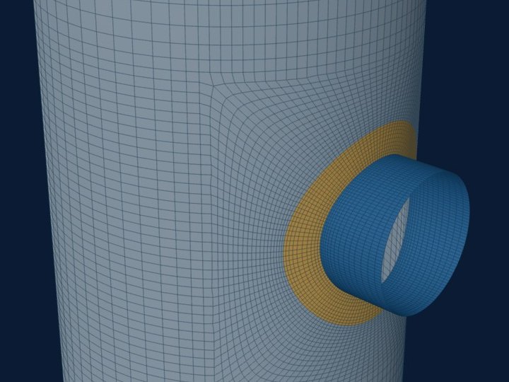
WRC 537 stops where its curves stop and where its assumptions stop holding: a shell too thin or too thick for the charts, an attachment too large, too close to a head, a cone junction or a neighbour, or a shape the bulletin never charted. Past those points a shell finite-element model of the same geometry gives the answer instead.
The calculator does not leave this to judgement. It sorts its own warnings into two kinds, and the results screen says which applies.
Two kinds of warning
Some limits mean the bulletin does not cover the case, so its result cannot be relied on. The calculator marks a shell model as required. Other limits mean WRC 537 still gives a result, but only by reading a curve at its edge. The calculator marks a shell model as suggested. A stated assumption, such as an offset nozzle or a pad, is printed with the result and does not by itself call for a model.
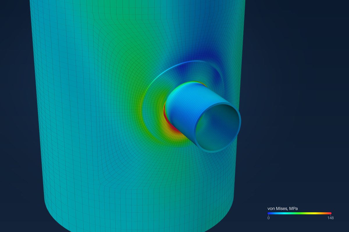
Where a shell model is required
- The shell is thinner than the curves cover: γ = Rm/T above 300.
- The cylinder is shorter than its mean radius. WRC 537, 4.5.1 says the results are not applicable.
- The attachment is closer than 0.5·Rm to the end of the cylinder, against WRC 537, 4.5.2.
- The nozzle is larger relative to the shell than any WRC 537 data, with di/Di above 0.6.
- A head nozzle outside the tabulated sphere curves, or beyond the limits of the spherical-shell theory, about a third of the head diameter.
- The attachment is in or too near the head knuckle. WRC 537 applies to the spherical part of the head only.
Where a shell model is suggested
- β above 0.5: the attachment is large for the shell, and the curve values are read at 0.5.
- γ below 5: the shell is thicker than the curves cover, and the values are read at γ = 5.
- A clip whose sides are more than 4 to 1: the values are read at the ratio limit.
- A nozzle-to-shell diameter ratio beyond the range of the bulletin's theory for cylinders, di/Di of about 0.25.
- A clip sized by an equivalent rectangle, once its stress ratio reaches 0.7, because the size itself is approximate.
A nozzle on a cone is treated as a nozzle on a cylinder of the local cone radius. The result says so and is marked approximate.
Limits no input can catch
Some limits come from the method's assumptions, and the inputs do not show them. WRC 537 takes each attachment as rigid and alone. Local bending dies out over a few decay lengths √(Rm·T): at 2.5 of them the envelope is down to about 4 % of its value at the edge. An attachment within that distance of a head, a cone junction, a seam or another attachment is no longer alone.
- Shapes the bulletin never charted: obround and tombstone openings, structural sections, tilted, lateral and tangential nozzles, a nozzle on a flat head.
- Stresses wanted in the nozzle or the pad, not only in the shell.
- A code route that calls for design by analysis rather than design by rule.
What the shell model does instead
The same inputs are carried across. The vessel becomes its mid-surface, meshed with four-node quadrilateral shell elements; the thickness is a property of each element, so one layer carries membrane force and bending together. Parts that meet share nodes, so the load crosses the junction through the mesh itself.
The mesh is set by the same decay length. The first element at a junction is the smaller of T and 0.2·√(R·T), the refined zone runs 2.5·√(R·T) from the attachment edge, and the far field grows to one √(R·T). Every model is checked for element shape, free edges and orientation before it is offered, and a mesh with folded elements is refused with the reason.
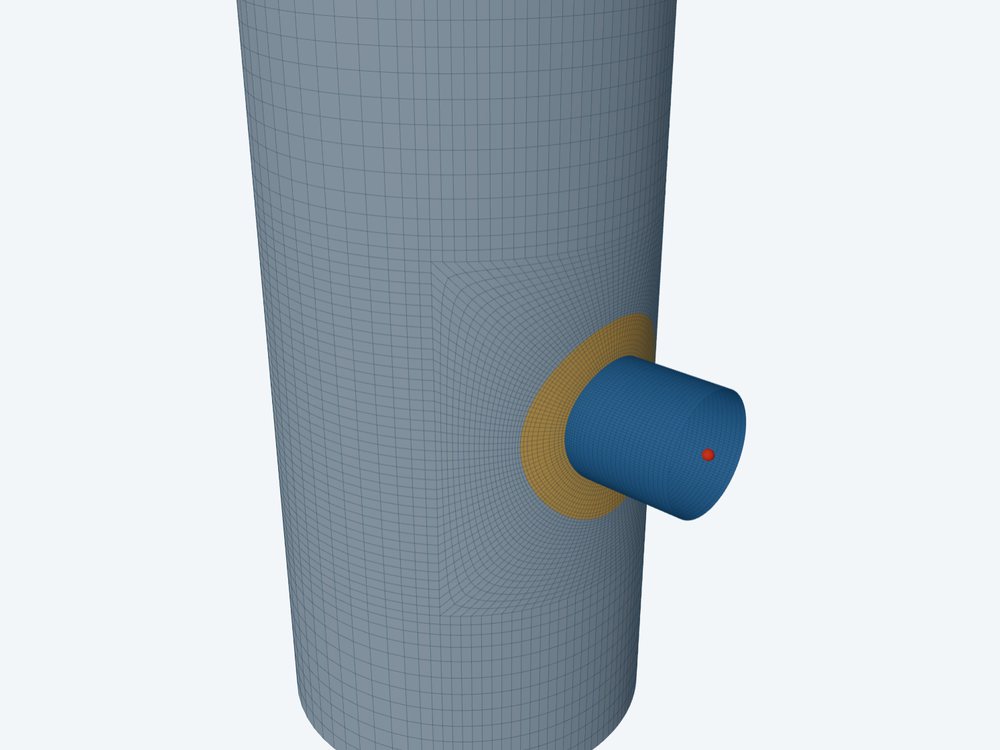
What the model buys is that the governing point is found, not assumed. Shell elements report membrane force and bending per unit length directly, so the membrane and bending split of ASME Section VIII Division 2, Part 5 comes out without a separate linearization. The model reports the nozzle and the pad as well as the shell.
Which to run first
The two are not alternatives to pick on taste. WRC 537 is the right answer whenever it applies: it is quick, it gives the same number every time, and it can be checked by hand. The shell model is for the cases where it does not apply, or where a WRC 537 result comes out close to the limit through a curve read at its edge.
Where it stops
- 01The shell model is linear and bonded: a pad that is not welded all round, or parts that only touch, are not modelled.
- 02Peak stress at a weld toe needs a solid model or a fatigue method of its own; a shell model does not resolve it.
- 03The finite-element results are early access and under verification. Until that is finished they are not a source of design values.
- 04Elastic-plastic analysis with large displacement, contact and dynamic loads are not attempted.
Try it in FEXLA
The Large, tilted or non-round opening card builds the shell model for openings past the bulletin's range, from the same inputs.
Open the cardReferences
- WRC Bulletin 537, 4.5 Limits on application (4.5.1 cylinder length, 4.5.2 distance from the end).
- ASME Section VIII Division 2, Part 5, Design by Analysis.
Method notes this draws on
Next post: Primary vs secondary stress at a nozzle (VIII-2 Table 5.6)
Educational article. It explains principles and is not design guidance; follow your governing code and edition.