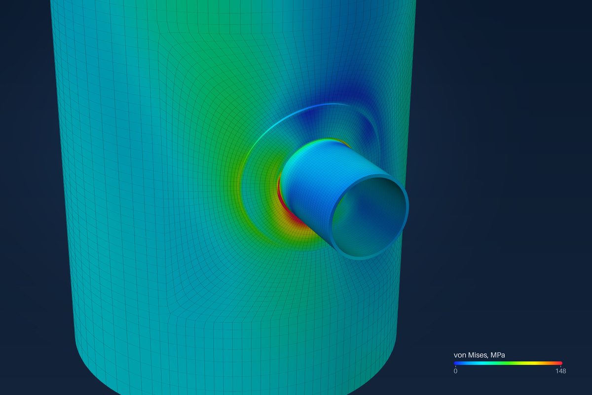
At a nozzle, the membrane stress the loads cause near the junction is local primary membrane stress, PL, limited to about 1.5S. The bending at the junction is secondary, Q, because it eases once the metal yields locally; with PL it is limited as a range to about 3S. ASME Section VIII Division 2 sorts them this way in Table 5.6, by where the stress is and what causes it.
This post sets out that sorting at a nozzle, and how the WRC 537 check and the shell model in FEXLA each apply it.
Why the stress is sorted at all
A stress that holds the loads in balance cannot relax: if it is too high, the shell yields through and keeps going. That is primary stress. A stress that exists only to make parts fit together relaxes once the metal yields a little; the parts then fit with less stress. That is secondary stress. The code gives primary stress tight limits and judges secondary stress by its range over a cycle.
The categories at a nozzle
| Symbol | Where | Typical limit |
|---|---|---|
| Pm | Shell away from the nozzle: the pressure design of the shell | S |
| PL | Membrane near the junction, from pressure and the nozzle loads | 1.5S |
| Pb | Bending that holds a load in balance, such as a flat plate under pressure | with PL, 1.5S |
| Q | Bending at the junction, thermal stress | PL + Pb + Q range, about 3S |
| F | Peak at the weld toe notch | Fatigue only |
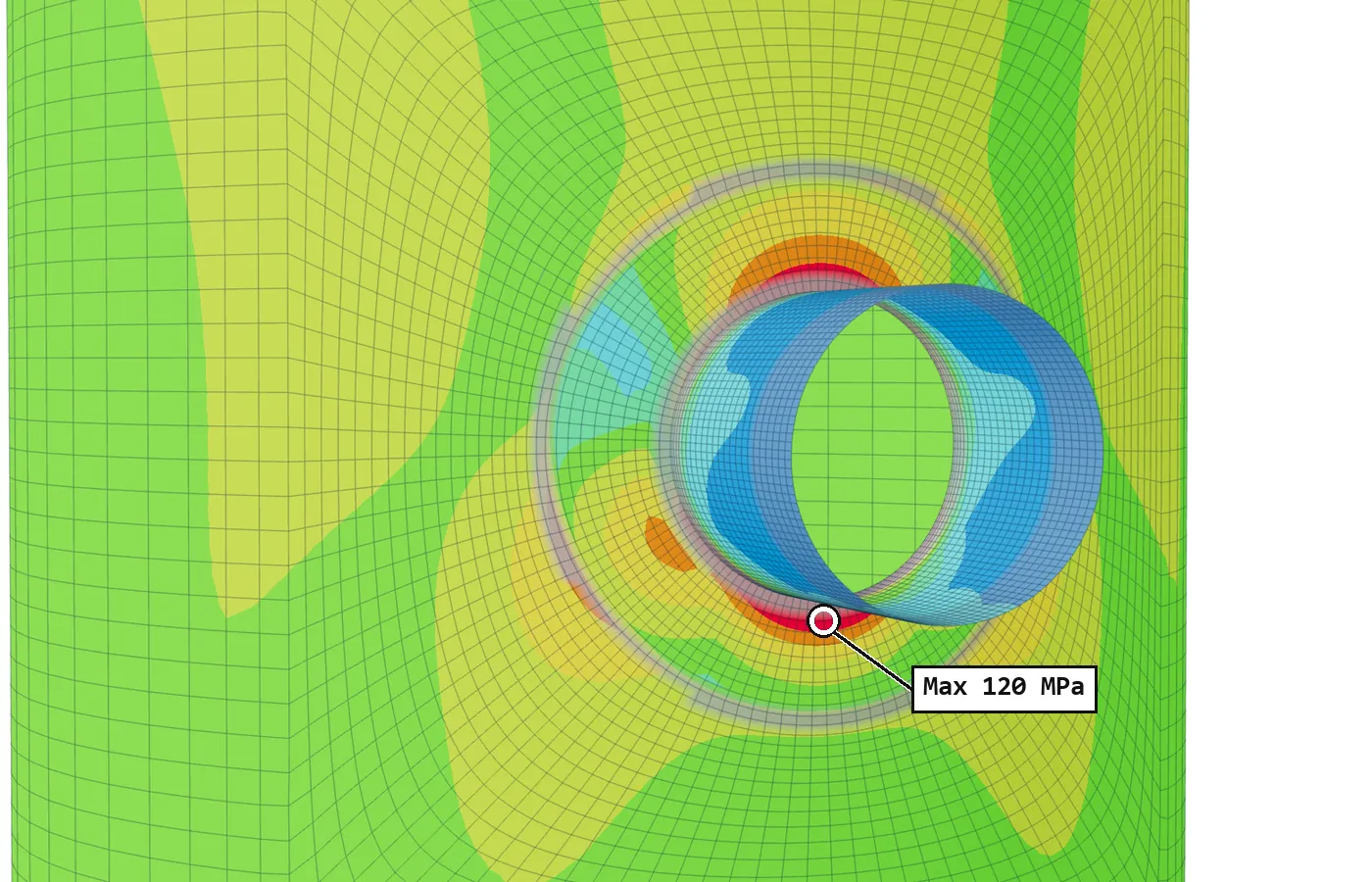
Local membrane stress is allowed above S only near the discontinuity. The shell model enforces that extent: beyond √(R·t) of the junction, membrane stress is checked as general membrane, Pm ≤ S, which keeps the rule that local membrane above 1.1S stays within √(R·t).
How the WRC 537 check applies it
WRC 537 gives membrane and bending at eight points round the nozzle. The membrane part, with the pressure membrane stress, is PL and is checked against 1.5S. The membrane plus bending at each surface is PL + Pb + Q and is checked against 3S by default. S is the shell allowable. On a clip with a pad, the lower of shell and pad applies at the clip edge, and the shell's alone at the pad edge, where only shell metal is present.
The 3S default assumes the loads relax as the shell deforms, as an imposed displacement does. If the nozzle loads are sustained, such as weight, pressure thrust, wind or seismic, the engineer can limit the surface stress to 1.5S, treating it like a primary stress, or choose a value between 1.5 and 3.0 where the design basis supports it. The PL ≤ 1.5S check does not change.
How the shell model applies it
The shell model reports results by zone: shell, nozzle and attachment at the junction (within √(R·t) of the weld line), the same parts away from it, and the pad's outer edge. Junction stresses are read at the weld toes, not on the model's intersection line, which lies inside the other part's wall.
- At the junction the membrane is PL, checked against SPL. Bending at the gross discontinuity is Q by default and does not enter the primary check. A conservative option counts it as primary bending, so PL + Pb ≤ 1.5S as well.
- Away from the junction the membrane is Pm ≤ S, except where Table 5.6 says otherwise: the knuckle of a formed head carries local membrane PL, and a flat plate's pressure bending is primary, Pm + Pb ≤ 1.5S.
- Thermal stress is always Q. It enters the operating ranges and fatigue, never the primary checks.
- Local failure is checked on the sum of the principal stresses, σ1 + σ2 + σ3 ≤ 4S.
The equivalent stress is von Mises by default, as the edition of Division 2 the tool is set to uses; Tresca stress intensity is offered for earlier editions. Tensors are combined first and the equivalent stress taken after.
Sorted by what causes it, not by its name
Table 5.6 classifies a stress by the load that causes it. The same operating row can be primary or secondary. Thermal expansion of a connected line is an imposed movement: self-limiting, so its stress is Q and it enters only the ranges. A load that must be carried whatever the shell does, such as an agitator's thrust, is load-controlled and primary. The shell model asks which it is and prints the classification it used in the report.
Occasional loads follow the same rule. Wind and earthquake inertia are primary. A seismic anchor movement or a support settlement is an imposed displacement, secondary, and checked as a range.
Where it stops
- 01WRC 537 has no peak stress and no fatigue; the shell model does not resolve the weld toe notch either. That needs a solid model or a fatigue method of its own.
- 02The classification at a junction is a choice the engineer confirms; the default follows Table 5.6, the conservative option counts junction bending as primary.
- 03S, Sy and Su are typed by the engineer from their own copy of ASME Section II Part D.
- 04Finite-element results are early access and under verification.
Try it in FEXLA
The Nozzle loads card runs the WRC 537 check with the 3S or 1.5S surface limit, and the shell model with the Table 5.6 classification printed in its report.
Open the cardReferences
- ASME Section VIII Division 2, Part 5: 5.2.2 (elastic stress analysis), Table 5.6 (stress classification), eq. (5.2) SPL, 5.3.2 (local failure), 5.5.5.2.1 eq. (5.95) SPS, 5.5.6.
- WRC Bulletin 537.
Method notes this draws on
Next post: Load sets: design, sustained, operating, occasional — what changes in the check
Educational article. It explains principles and is not design guidance; follow your governing code and edition.